
User Guide

T-3100/T-3200/T-3300 Technical Bulletin 11
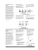
C. In-Line Restrictor -
R-3710-1007 Required as a
replacement for restrictor “T”
fittings on copper tubing
installations. Installation
instructions covered on
page 6. “T” fitting W/.007”
restrictor R-3710-3107 to
replace restrictor “T” on
T-3100, T-3110, T-3200 and
T-3250 thermostats.
D. Direct Acting Lid -
T-3100-601
E. Reverse Acting Lid -
T-3100-606
F. Low Limit Lid - T-3100-602
It will be necessary to
remove the low limit flexure
lever and the spacer below it
in order to remove this item.
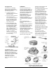
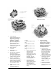
G. Screw Kit - T-3100-600
This kit consists of three (3)
screws 5/16 in. long, indicated
by G1 and seven (7) screws
3/16 in. long, indicated by G2
in the illustrations above.
H. Switch Stacks for T-3200
Series:
T-3200-600 switches at
17 psig
T-3250-600 switches at 13
psig
Switch Stacks for T-3300
Series:
T-3300-600 switches at 13
psig
T-3350-600 switches at 17
psig
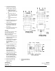
1. Before removing the four
mounting screws,
carefully note the
position of the “V” notch
of the stack in relation to
the thermostat
assembly. The new
stack must be placed in
the same position.
2. After placing the new
stack in the correct
position, tighten the four
mounting screws in a
crisscross pattern so
that the gasket is loaded
evenly.
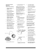
I. Element Assembly
T-285-600 Averaging
Element (used as low limit
element on two element
controllers) T-275-602 Bulb
Element T-276-600 Remote
Adjustment Assembly
including Bulb Element.
1. Remove the DIR
adjusting screw bracket;
the DIR lid; the REV lid;
the screws (2) holding
the flexure lever; and
unhook the spring
holding the flexure lever.
2. Remove the flexure lever
exposing the clip and
screw holding the
element capillary. Also
remove the clip and
screw.
3. Remove and save the
element spacer button,
and lift the element from
the socket.
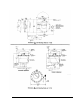
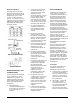
Adjusting Screw Location
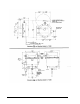
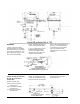
Repair Details
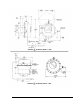
Repair Parts Location