
User Guide

10 T-3100/T-3200/T-3300 Technical Bulletin
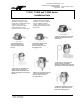
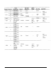
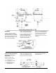
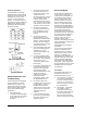
Restricted Adjustment
The dial pointer on externally
adjusted models has tabs which
are factory set to restrict the dial
adjustment to a span of 15F°
(7-1/2F° on either side of the
pointer). The restriction can be
changed to the spans indicated in
table below by bending up the
appropriate tabs and flattening
the factory set tabs.
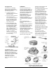
Routine Maintenance and
Troubleshooting
These instruments are designed
so that a minimum of routine
maintenance is required. The
following procedures should be
used to insure proper operation
and to locate malfunctioning
components.
1. Check all air lines,
connections and diaphragms
for air leaks. Be sure that the
in-line restrictors are not
defective.
2. Check the operation of the
thermostat to be sure it is
passing the correct control
signal and that it is
functioning properly. Be sure
it has the proper supply air
pressure and that air is
exhausting from the control
port. The port must exhaust
continuously to insure proper
operation of the thermostat.
3. Be sure the temperature
measuring element has not
been damaged or moved
from its intended sensing
position.
4. Be sure the actuator is
stroking properly. Do not
lubricate the actuator shaft; it
slides in a factory lubricated
bearing. Be sure all stops
and locking devices are tight
and have not moved.
5. Check all linkages to be sure
there is no binding and that
operation is free and
unrestricted throughout the
entire stroke.
6. Be sure the damper blades
are not obstructed and are in
good repair. Clean all pivots
and remove any rust
corrosion or paint from the
blade edges.
7. Be sure the valve packing nut
is tight enough to prevent
leaks, but not so tight that
the packing becomes
distorted and binds the stem;
usually finger tight is
sufficient. If the valve is
leaking around the
centerpiece, tighten it with
the appropriate wrench.
8. Be sure the valve seats
completely when the actuator
is fully stroked. If there is
fluid flow after the plug is
seated, the seat, plug or disc
may be worn or scored and
should be repaired or
replaced.
9. If there are slave actuators,
be sure they are operating in
the proper sequence and
adjusted correctly.
Service and Repair
Descriptions and specifications
for the T-3100, T-3200 and
T-3300 Series instruments with
and without integral actuators,
and for Johnson valves and
damper actuators are found in
their respective Product Data
sheets. It is important that the
instrument be identified before
servicing so that related literature
such as repair parts sheets can
be reviewed. All jobs have
control diagrams and records on
file that list the exact units used in
the control system according to
Product Data sheet number,
function, and in the case of
actuators, spring range.
Reference must always be made
to the Repair Parts Catalog for all
replacement parts,
subassemblies and complete
assemblies.
The tool section of the catalog
should be consulted for the
appropriate tools to use when
performing the various service
functions. In addition to the
instructions in this bulletin, in the
Operator’s Manual, and in other
Johnson Controls publications,
most repair kits contain specific
instructions. These instructions
must be followed exactly if proper
installation of the part is to be
accomplished.
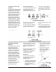
Thermostats
The following repair parts are
available for this series of
instruments from the factory:
A. Control Port(s) - T-4002-600
To remove and install this
item use control port wrench
X-200-16. In most cases it
will be necessary to remove
the associated lid.
B. Orifice Filter - T-3100-605
Use a sharp, pointed
instrument to remove this
item when plugged with dirt.
Use the eraser end of a
pencil or some other blunt
device to install the new filter.