
Inc. Air Conditioner User Manual


505430-BTG-A-0309
Johnson Controls Unitary Products 91
NOTE: The ‘I’ designation indicates a four pipe system.
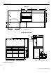
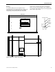
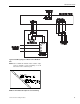
PIPING AND ELECTRICAL CONNECTIONS
Piping connections are made from the rear of 7.5 thru 12.5
Ton units and the front of 15 thru 20 Ton units. Connections
can be made directly to the suction and liquid line service
valves.
With the piping connections being made at the rear of 7.5
thru 12.5 Ton units and the front of 15 thru 20 Ton units, the
piping can be routed to the units from the left or right side.
Electrical connections for power and control wiring are made
from the front of the units, right or left of 7.5 thru 12.5 Ton
electrical control box access or left of the electrical control
box access on 15 thru 20 Ton units. See Unit Dimensions
and Piping and Electrical Connection Sizes tables for piping
sizes and electrical knockout details.
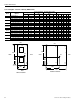
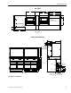
Unit Dimensions
MODEL A B C D DI E EI F FI G GI H I J K L M N O P Q R S
PH-15 59.1 64.1 44.5 13.8 N/A 13.4 N/A 20.2 N/A 23.9 N/A 15.0 12.5 11.4 8.4 2.4 3.9 22.0 2.9 4.9 7.1 4.8 14.7
PJ-15 59.1 64.1 44.5 13.7 10.1 13.3 9.7 10.3 18.8 24.2 22.0 15.0 12.5 11.4 8.4 2.1 3.6 22.0 2.9 4.9 7.1 4.8 14.7
PH-20 59.1 64.1 50.0 13.8 N/A 13.4 N/A 20.2 N/A 23.9 N/A 15.0 12.5 11.4 8.4 2.1 3.6 22.0 2.9 4.9 7.1 4.8 14.7
PJ-20 59.1 64.1 50.0 14.0 10.5 13.5 9.9 20.3 18.8 24.1 22.0 15.0 12.5 11.4 8.4 2.1 3.6 22.0 2.9 4.9 7.1 4.8 14.7
YH-15 59.1 64.1 44.5 13.4 N//A 13.4 N/A 20.2 N/A 24.1 N/A 15.0 12.5 11.4 8.4 2.1 3.6 22.0 2.9 4.9 7.1 4.8 14.7
YJ-15 59.1 64.1 44.5 13.1 9.6 12.9 9.4 20.2 18.7 24.2 22.0 15.0 12.5 11.4 8.4 2.1 3.6 22.0 2.9 4.9 7.1 4.8 14.7
YH-20 59.1 64.1 50.0 13.5 N/A 13.4 N/A 20.2 N/A 24.2 N/A 15.0 12.5 11.4 8.4 2.1 3.6 22.0 2.9 4.9 7.1 4.8 14.7
YJ-20 59.1 64.1 50.0 13.1 9.6 12.9 9.4 20.2 18.7 24.2 22.0 15.0 12.5 11.4 8.4 2.1 3.6 22.0 2.9 4.9 7.1 4.8 14.7
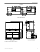
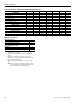
UNIT CLEARANCES
Location Dimensions
Overhead (Top)
1
1
Units must be installed outdoors. Overhanging structures or
shrubs should not obstruct condenser air discharge.
120”
Front access panels 36”
Left Side 30”
Right Side 30”
Rear 24”
Bottom
2
0”
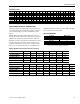
Piping And Electrical Connection Sizes (Inches)
MODEL PH-07 YH-07 PH-10 YH-10 YJ-10 YH-12 YJ-12
No. Refrigeration Circuits 1111212
Suction Line OD (in.) 1 1/8 1 1/8 1 1/8 1 3/8 1 1/8 1 3/8 1 1/8
Liquid Line OD (in.) 5/8 5/8 5/8 7/8 5/8 7/8 5/8
Power Wiring Knockout 1 3/8 1 3/8 1 3/8 1 3/8 1 3/8 1 3/8 1 3/8
Control Wiring Knockout 7/8 7/8 7/8 7/8 7/8 7/8 7/8
MODEL PH-15 PJ-15 PH-20 PJ-20 YH-15 YJ-15 YH-20 YJ-20
No. Refrigeration Circuits 12121212
Suction Line OD (in.) 1 5/8 1 1/8 1 5/8 1 3/8 1 5/8 1 1/8 1 5/8 1 3/8
Liquid Line OD (in.) 7/8 5/8 7/8 7/8 7/8 5/8 7/8 7/8
Power Wiring Knockout 1 3/8 1 3/8 1 3/8 1 3/8 1 3/8 1 3/8 1 3/8 1 3/8
Control Wiring Knockout 7/8 7/8 7/8 7/8 7/8 7/8 7/8 7/8