505430-BTG-A-0309 TECHNICAL GUIDE Description UP condensing units and heat pumps are completely assembled, piped and wired at the factory to provide a single-piece unit for shipment and rigging. Each unit is pressurized with a holding charge of refrigerant R-410A for storage and/or shipping.
505430-BTG-A-0309 Table of Contents Description . . . . . . . . . . . . . . . . . . . . . . . . . . . . . . . . . . . . . . . . . . . . . . . . . . . . . . . . . . . . . . . . . . . . . . . . . . . . . . . . . . . . . . . . . 1 Table of Contents . . . . . . . . . . . . . . . . . . . . . . . . . . . . . . . . . . . . . . . . . . . . . . . . . . . . . . . . . . . . . . . . . . . . . . . . . . . . . . . . . . . . 2 Nomenclature . . . . . . . . . . . . . . . . . . . . . . . . . . . . . . . . . . . . . . . . .
505430-BTG-A-0309 Nomenclature Configured Split Condenser Model Number Nomenclature Y H -20 C00 A T A AA 2 A Product Style A = Style A Product Category Y = Split System, Condenser, AC, R-410A P = Split System, Condenser, HP, R-410A Product Generation 1 = First Generation Product Identifier H = Standard Efficiency, 2-Pipe, R-410A J = Standard Efficiency, 4-Pipe, R-410A Nominal Cooling Capacity - MBH -07 = 7.5 Ton -10 = 10 Ton -12 = 12.
505430-BTG-A-0309 Condensing Unit Features and Benefits • Factory installed powered or non-powered 115 volt GFI outlet. Features • Factory installed phase monitor to protect the unit from phase loss or phase reversal. • Meets or exceeds ASHRAE 90.1 standards. • Scroll compressors provide both high efficiency and reliability. • Simplicity ® Controls • Dual refrigerant circuits on PJ and YJ models.
05430-BTG-A-0309 Air Handling Unit Features and Benefits Features These air handlers can be arranged for a variety of air discharge patterns in either the horizontal or vertical position. Refer to the unit installation instructions for other application possibilities. Benefits Air handling units are designed with two distinct modules to provide maximum application flexibility. All are shipped as single packages with the blower module mounted on top of the coil module.
505430-BTG-A-0309 Guide Specifications Split System Cooling Only Condensing Units Models: YH-07 thru -20, YJ-10 thru -20 & Split System Heat Pump Models: PH-07 thru -20, PJ-15 thru -20 General Unit Construction • Constructed of zinc-coated, galvanized steel. • Exterior surfaces bonded and coated with baked enamel finish by a powder paint process capable of withstanding a minimum of 1000 salt spray hours according to ASTM B117.
505430-BTG-A-0309 • Must cycle to allow cooling operation down to 40°F. Refrigerant Piping • Solid core filter-drier(s) ship loose for field installation. Convenience Outlet • Factory-installed, internally mounted. • Accessible from outside the unit. • Liquid and suction line service valves with gauge ports. • 115V, 15 amp GFI receptacle with independent fuse protection. • Suction and discharge line service ports accessible from unit. Ports capped for leak prevention.
505430-BTG-A-0309 • The minimum application clearances for condensing units, heat pumps and air handlers must meet those specified in the manufacturer’s literature. The Blower Motor Shall: • Be mounted within the insulated cabinet to minimize the transmission of sound to the surrounding space, and any motor 7.5 HP or greater must have a service factor of 1.15.
505430-BTG-A-0309 Physical Data YH-07 Thru -20 and YJ-10 Thru -20 Physical Data Component Nominal Tonnage REFRIGERANT Refrigerant type Holding charge (lb)1 Operating Charge (lb)2 System #1 System #2 DIMENSIONS (inches) Length Width Height WEIGHTS (lb) Shipping Operating COMPRESSORS Type Quantity Nominal Capacity (Tons) Capacity Stages System #1 System #2 System #1 System #2 SYSTEM DATA No. Refrigeration Circuits Suction Line OD (in.) Liquid Line OD (in.) OUTDOOR COIL DATA Face area (Sq. Ft.
505430-BTG-A-0309 PH-07 Thru -20 and PJ-15 Thru -20 Physical Data Models Component Nominal Tonnage REFRIGERANT Refrigerant type Holding charge (lb)1 Operating Charge (lb)2 System #1 System #2 PH-07 7.5 PH-10 10 PH-15 15 PJ-15 15 PH-20 20 PJ-20 20 R-410A 1.0 16.1 --- R-410A 1.0 23.3 --- R-410A 1.0 35.7 --- R-410A 1.0 17.9 17.9 R-410A 1.0 44.2 --- R-410A 1.0 22.1 22.1 59.1 31.9 44.5 59.1 31.9 50.0 59.1 64.1 44.5 59.1 64.1 44.5 59.1 64.1 50.0 59.1 64.1 50.
505430-BTG-A-0309 Physical Data Indoor Unit NH-07 7 1/2 NH-10 10 NJ-10 10 Models NH-15 15 NJ-15 15 NH-20 20 NJ-20 20 Length 30.0 30.0 30.0 33.0 33.0 30.0 30.0 Width 56.0 56.0 56.0 74.5 74.5 98.5 98.5 Height 65.0 65.0 65.0 75.0 75.0 65.0 65.
505430-BTG-A-0309 Unit Limitations Condenser Unit limitations Size (Tons) Model -07 (7.5) PH -07 (7.5) YH -10 (10) PH -10 (10) YH/YJ -12 (12.
505430-BTG-A-0309 Air Handling Unit Limitations Entering Air Temperature Degrees °F Model NH-07 NH-10 NJ-10 NH-15 NJ-15 NH-20 NJ-20 1 Power Supply Voltage Voltage Variation Supply Air Range CFM Cooling DB/WB Heating DB1 Min. Max. Min. Max. Min. Max. Min. Max.
505430-BTG-A-0309 Cooling and Heating Ratings Cooling And Heating Rating System Cooling Capacity1 Condensing Unit Only Outdoor Unit Gross Capacity2 (MBH) KW EER Indoor Unit Heating Capacity1 High Outdoor Gross Capacity3 (MBH) EER IEER IPLV Gross Capacity2 (MBh) COP Low Outdoor Gross Capacity2 (MBh) COP Rated Airflow (CFM) PH-104 N/A N/A N/A NH-07 92 11.0 11.4 --- 82 3.3 49 2.3 3000 PH-104 N/A N/A N/A NH-10 124 11.0 11.4 11.8 109 3.3 63 2.
505430-BTG-A-0309 Capacity Performance Condenser and Air Handling Cooling Capacities YH-07 / NH-07 Air on Evaporator Coil CFM 2250 2625 3000 3375 3750 2250 2625 3000 3375 3750 WB (°F) Total Capacity1 (MBh) Total Input (kW)2 77 72 67 62 57 77 72 67 62 57 77 72 67 62 57 72 67 62 57 72 67 62 57 110.8 103.3 95.9 88.0 77.7 114.0 106.3 98.7 90.6 79.9 117.2 109.3 101.4 93.1 82.2 109.2 101.3 93.0 82.1 109.1 101.2 92.9 82.0 6.0 5.7 5.5 5.4 5.2 6.0 5.7 5.4 5.4 5.2 5.9 5.7 5.4 5.4 5.2 5.8 5.5 5.5 5.
505430-BTG-A-0309 YH-07 / NH-07 (Continued) Air on Evaporator Coil CFM 2250 2625 3000 3375 3750 1 2 16 WB (°F) Total Capacity1 (MBh) Total Input (kW)2 77 72 67 62 57 77 72 67 62 57 77 72 67 62 57 72 67 62 57 72 67 62 57 94.7 87.8 80.9 74.3 75.0 97.0 89.9 82.8 76.1 76.8 99.2 92.0 84.8 77.8 78.6 92.2 84.9 78.0 78.7 92.3 85.1 78.1 78.9 9.0 9.1 9.1 8.8 8.9 9.1 9.1 9.2 8.8 9.0 9.1 9.2 9.2 8.9 9.0 9.2 9.2 8.9 9.0 9.1 9.2 8.9 9.
505430-BTG-A-0309 YH-07 / NH-10 Air on Evaporator Coil CFM 2250 2625 3000 3375 3750 2250 2625 3000 3375 3750 WB (°F) Total Capacity1 (MBh) Total Input (kW)2 90 77 72 67 62 57 77 72 67 62 57 77 72 67 62 57 72 67 62 57 72 67 62 57 105.1 100.1 95.1 87.9 83.1 109.8 104.5 99.3 91.8 86.7 114.5 109.0 103.5 95.7 90.4 110.2 104.6 96.7 91.4 111.4 105.8 97.8 92.4 6.0 5.8 5.7 5.6 5.5 6.0 5.9 5.7 5.6 5.6 6.1 5.9 5.8 5.7 5.6 6.0 5.8 5.7 5.6 6.0 5.9 5.7 5.7 49.2 63.3 77.3 87.9 83.1 53.6 68.6 83.5 91.
505430-BTG-A-0309 YH-07 / NH-10 (Continued) Air on Evaporator Coil CFM 2250 2625 3000 3375 3750 1 2 18 WB (°F) Total Capacity1 (MBh) Total Input (kW)2 77 72 67 62 57 77 72 67 62 57 77 72 67 62 57 72 67 62 57 72 67 62 57 103.1 95.4 87.6 80.6 79.5 106.1 98.2 90.3 83.0 81.8 109.2 101.0 92.9 85.4 84.2 103.1 94.7 87.1 85.9 105.1 96.6 88.8 87.6 9.1 9.0 8.9 8.7 8.6 9.2 9.1 9.0 8.8 8.7 9.3 9.2 9.1 8.9 8.8 9.2 9.1 9.0 8.8 9.2 9.1 9.0 8.
505430-BTG-A-0309 YH-10 / NH-10 Air on Evaporator Coil CFM 3000 3500 4000 4500 5000 3000 3500 4000 4500 5000 WB (°F) Total Capacity1 (MBh) Total Input (kW)2 90 77 72 67 62 57 77 72 67 62 57 77 72 67 62 57 72 67 62 57 72 67 62 57 142.3 133.9 125.5 115.0 111.2 151.4 142.4 133.4 122.3 118.3 160.5 150.9 141.4 129.6 125.4 154.4 144.7 132.6 128.3 157.9 148.0 135.6 131.2 7.5 7.4 7.3 7.3 7.2 7.5 7.4 7.3 7.3 7.2 7.5 7.4 7.3 7.3 7.2 7.5 7.4 7.3 7.3 7.5 7.4 7.3 7.3 64.7 84.4 104.0 115.0 111.2 72.
505430-BTG-A-0309 YH-10 / NH-10 (Continued) Air on Evaporator Coil CFM 3000 3500 4000 4500 5000 1 2 20 WB (°F) Total Capacity1 (MBh) Total Input (kW)2 90 77 72 67 62 57 77 72 67 62 57 77 72 67 62 57 72 67 62 57 72 67 62 57 117.5 109.1 100.8 94.0 94.0 124.2 115.4 106.6 99.4 99.4 131.0 121.7 112.3 104.8 104.8 124.7 115.2 107.4 107.4 127.8 118.0 110.1 110.1 12.0 11.9 11.9 11.8 11.8 12.0 11.9 11.9 11.8 11.8 12.0 11.9 11.9 11.8 11.8 11.9 11.9 11.8 11.8 12.0 11.9 11.8 11.9 63.4 81.0 98.6 94.0 94.
505430-BTG-A-0309 YJ-10 / NJ-10 Air on Evaporator Coil CFM 3000 3500 4000 4500 5000 3000 3500 4000 4500 5000 WB (°F) Total Capacity1 (MBh) Total Input (kW)2 90 77 72 67 62 57 77 72 67 62 57 77 72 67 62 57 72 67 62 57 72 67 62 57 138.1 130.1 122.0 112.3 108.2 147.1 138.4 129.8 119.5 115.1 156.0 146.8 137.7 126.8 122.1 152.4 142.9 131.5 126.7 157.9 148.1 136.3 131.3 7.5 7.4 7.2 7.2 7.1 7.5 7.4 7.3 7.2 7.2 7.6 7.4 7.3 7.2 7.2 7.5 7.3 7.2 7.2 7.5 7.4 7.3 7.3 63.6 82.9 102.2 112.3 108.2 70.
505430-BTG-A-0309 YJ-10 / NJ-10 (Continued) Air on Evaporator Coil CFM 3000 3500 4000 4500 5000 1 2 22 WB (°F) Total Capacity1 (MBh) Total Input (kW)2 90 77 72 67 62 57 77 72 67 62 57 77 72 67 62 57 72 67 62 57 72 67 62 57 116.8 106.7 96.6 89.7 93.0 122.7 112.1 101.4 94.2 97.7 128.6 117.4 106.3 98.8 102.3 122.9 111.2 103.3 107.1 128.3 116.1 107.9 111.8 12.1 11.9 11.8 11.7 11.7 12.1 11.9 11.8 11.7 11.7 12.1 11.9 11.8 11.7 11.7 12.0 11.8 11.7 11.7 12.0 11.9 11.7 11.8 58.7 75.9 93.2 89.7 93.
505430-BTG-A-0309 YH-12 / NH-15 Air on Evaporator Coil CFM 3750 4375 5000 5625 6250 3750 4375 5000 5625 6250 WB (°F) Total Capacity1 (MBh) Total Input (kW)2 90 77 72 67 62 57 77 72 67 62 57 77 72 67 62 57 72 67 62 57 72 67 62 57 178.5 168.2 157.9 144.8 149.7 184.7 174.0 163.4 149.9 154.9 190.9 179.9 168.8 154.9 160.1 182.3 171.1 157.0 162.2 184.7 173.4 159.0 164.4 10.2 9.9 9.6 9.4 9.5 10.2 9.9 9.6 9.4 9.5 10.3 9.9 9.6 9.4 9.6 10.1 9.8 9.6 9.7 10.2 9.9 9.7 9.8 87.6 111.9 136.1 144.8 149.
505430-BTG-A-0309 YH-12 / NH-15 (Continued) Air on Evaporator Coil CFM 3750 4375 5000 5625 6250 1 2 24 WB (°F) Total Capacity1 (MBh) Total Input (kW)2 90 77 72 67 62 57 77 72 67 62 57 77 72 67 62 57 72 67 62 57 72 67 62 57 153.8 142.2 130.5 128.2 131.2 155.5 143.8 132.0 129.7 132.7 157.3 145.4 133.5 131.1 134.2 149.5 137.3 134.8 138.0 153.6 141.0 138.5 141.8 15.8 15.5 15.1 15.1 15.2 15.7 15.3 15.0 15.0 15.1 15.5 15.2 14.9 14.9 15.0 15.4 15.1 15.1 15.2 15.6 15.3 15.3 15.4 77.6 101.0 124.
505430-BTG-A-0309 YJ-12 / NJ-15 Air on Evaporator Coil CFM 3750 4375 5000 5625 6250 3750 4375 5000 5625 6250 WB (°F) Total Capacity1 (MBh) Total Input (kW)2 90 77 72 67 62 57 77 72 67 62 57 77 72 67 62 57 72 67 62 57 72 67 62 57 170.2 164.1 157.9 142.4 141.3 182.4 175.5 168.7 152.3 151.2 194.5 187.0 179.5 162.2 161.1 187.6 180.3 162.8 161.6 188.2 181.0 163.3 162.1 10.0 9.7 9.5 9.3 9.3 10.0 9.7 9.5 9.4 9.3 10.0 9.8 9.5 9.4 9.4 9.8 9.6 9.5 9.4 9.9 9.7 9.5 9.5 80.1 106.1 132.0 142.4 141.
505430-BTG-A-0309 YJ-12 / NJ-15 (Continued) Air on Evaporator Coil CFM 3750 4375 5000 5625 6250 1 2 26 WB (°F) Total Capacity1 (MBh) Total Input (kW)2 90 77 72 67 62 57 77 72 67 62 57 77 72 67 62 57 72 67 62 57 72 67 62 57 148.6 138.6 128.6 119.7 123.4 155.4 145.0 134.5 125.3 129.1 162.3 151.3 140.4 130.8 134.8 154.3 143.2 133.4 137.4 157.3 146.0 136.0 140.1 15.3 15.1 14.8 14.5 14.7 15.4 15.1 14.8 14.5 14.7 15.4 15.1 14.8 14.5 14.7 15.2 14.9 14.6 14.8 15.3 15.0 14.7 14.9 73.8 97.6 121.
505430-BTG-A-0309 YH-15 / NH-15 Air on Evaporator Coil CFM 4500 5250 6000 6750 7500 4500 5250 6000 6750 7500 WB (°F) Total Capacity1 (MBh) Total Input (kW)2 90 77 72 67 62 57 77 72 67 62 57 77 72 67 62 57 72 67 62 57 72 67 62 57 223.5 207.2 191.0 176.0 175.0 229.4 212.8 196.1 180.7 179.7 235.4 218.3 201.2 185.4 184.4 221.3 204.0 187.9 186.8 224.2 206.7 190.4 189.3 11.8 11.5 11.1 10.8 10.8 11.9 11.6 11.2 11.0 10.9 12.0 11.7 11.3 11.1 11.0 11.3 11.0 10.7 10.6 10.9 10.6 10.3 10.3 104.0 132.
505430-BTG-A-0309 YH-15 / NH-15 (Continued) Air on Evaporator Coil CFM 4500 5250 6000 6750 7500 1 2 28 WB (°F) Total Capacity1 (MBh) Total Input (kW)2 90 77 72 67 62 57 77 72 67 62 57 77 72 67 62 57 72 67 62 57 72 67 62 57 185.3 170.5 155.8 145.5 147.3 189.1 174.1 159.0 148.5 150.4 192.9 177.6 162.2 151.5 153.4 179.0 163.5 152.7 154.7 180.4 164.8 153.9 155.9 17.5 17.3 17.1 16.9 16.8 17.6 17.4 17.2 17.0 16.9 17.7 17.5 17.3 17.0 17.0 17.5 17.3 17.0 17.0 17.5 17.3 17.0 17.0 92.7 119.4 146.
505430-BTG-A-0309 YH-15 / NH-20 Air on Evaporator Coil CFM 4500 5250 6000 6750 7500 4500 5250 6000 6750 7500 WB (°F) Total Capacity1 (MBh) Total Input (kW)2 90 77 72 67 62 57 77 72 67 62 57 77 72 67 62 57 72 67 62 57 72 67 62 57 214.3 201.7 189.0 181.2 177.1 220.7 207.6 194.6 186.5 182.3 227.1 213.6 200.2 191.9 187.6 218.3 204.5 196.0 191.6 223.0 208.9 200.2 195.7 12.1 11.8 11.6 11.3 11.3 12.2 11.9 11.7 11.4 11.4 12.3 12.0 11.8 11.5 11.5 12.1 11.9 11.6 11.6 12.2 11.9 11.7 11.6 111.5 138.
505430-BTG-A-0309 YH-15 / NH-20 (Continued) Air on Evaporator Coil CFM 4500 5250 6000 6750 7500 1 2 30 WB (°F) Total Capacity1 (MBh) Total Input (kW)2 90 77 72 67 62 57 77 72 67 62 57 77 72 67 62 57 72 67 62 57 72 67 62 57 203.2 187.4 171.6 153.7 157.8 208.6 192.4 176.2 157.8 162.0 214.1 197.4 180.8 162.0 166.3 200.5 183.6 164.5 168.8 203.6 186.4 167.0 171.4 18.8 18.3 17.7 17.2 17.1 19.0 18.4 17.8 17.3 17.2 19.1 18.5 17.9 17.4 17.3 18.5 17.9 17.4 17.3 18.5 17.9 17.4 17.3 106.1 131.7 157.
505430-BTG-A-0309 YJ-15 / Two NH-07 Air on Evaporator Coil CFM 4500 5250 6000 6750 7500 4500 5250 6000 6750 7500 WB (°F) Total Capacity1 (MBh) Total Input (kW)2 90 77 72 67 62 57 77 72 67 62 57 77 72 67 62 57 72 67 62 57 72 67 62 57 216.0 200.4 184.8 173.1 165.6 222.3 206.2 190.2 178.1 170.4 228.6 212.1 195.6 183.2 175.2 216.4 199.6 186.9 178.8 220.7 203.5 190.6 182.4 12.0 11.7 11.4 11.2 11.1 12.1 11.8 11.5 11.2 11.2 12.1 11.9 11.6 11.3 11.3 11.9 11.6 11.4 11.3 12.0 11.7 11.4 11.4 105.
505430-BTG-A-0309 YJ-15 / Two NH-07 (Continued) Air on Evaporator Coil CFM 4500 5250 6000 6750 7500 1 2 32 WB (°F) Total Capacity1 (MBh) Total Input (kW)2 90 77 72 67 62 57 77 72 67 62 57 77 72 67 62 57 72 67 62 57 72 67 62 57 193.0 179.5 166.0 154.6 151.8 198.9 185.0 171.0 159.2 156.4 204.7 190.4 176.1 163.9 161.0 192.4 177.9 165.6 162.6 194.3 179.7 167.3 164.3 17.7 17.4 17.1 16.8 16.8 17.8 17.5 17.2 16.9 16.9 17.9 17.6 17.2 17.0 17.0 17.6 17.3 17.1 17.0 17.7 17.4 17.1 17.1 96.7 121.8 146.
505430-BTG-A-0309 YJ-15 / Two NH-10 Air on Evaporator Coil CFM 6000 7000 8000 9000 10000 6000 7000 8000 9000 10000 Temperature of Air on Condenser Coil Sensible Capacity (MBh)1 WB (°F) Total Capacity1 (MBh) Total Input (kW)2 90 77 72 67 62 57 77 72 67 62 57 77 72 67 62 57 72 67 62 57 72 67 62 57 241.0 222.0 203.0 191.6 189.3 247.3 227.8 208.3 196.6 194.3 253.6 233.6 213.6 201.6 199.3 238.5 218.1 205.8 203.4 243.3 222.5 210.0 207.6 12.0 11.7 11.4 11.2 11.2 12.1 11.8 11.5 11.2 11.3 12.
505430-BTG-A-0309 YJ-15 / Two NH-10 (Continued) Air on Evaporator Coil CFM 6000 7000 8000 9000 10000 1 2 34 Temperature of Air on Condenser Coil Sensible Capacity (MBh)1 WB (°F) Total Capacity1 (MBh) Total Input (kW)2 90 77 72 67 62 57 77 72 67 62 57 77 72 67 62 57 72 67 62 57 72 67 62 57 226.4 210.6 194.9 185.6 185.6 228.3 212.4 196.5 187.1 187.1 230.2 214.2 198.2 188.7 188.7 216.2 200.1 190.5 190.5 218.3 202.0 192.3 192.3 15.9 15.6 15.3 15.0 15.0 17.1 16.8 16.5 16.2 16.2 18.3 18.0 17.
505430-BTG-A-0309 YJ-15 / NJ-15 Air on Evaporator Coil CFM 4500 5250 6000 6750 7500 4500 5250 6000 6750 7500 WB (°F) Total Capacity1 (MBh) Total Input (kW)2 90 77 72 67 62 57 77 72 67 62 57 77 72 67 62 57 72 67 62 57 72 67 62 57 208.6 198.3 188.0 170.5 177.8 217.2 206.4 195.7 177.6 185.1 225.8 214.6 203.4 184.6 192.4 214.6 203.4 184.6 192.4 214.6 203.5 184.6 192.5 11.7 11.4 11.0 10.9 11.0 11.7 11.4 11.1 10.9 11.0 11.8 11.4 11.1 11.0 11.1 11.5 11.2 11.1 11.1 11.6 11.3 11.1 11.2 106.3 132.
505430-BTG-A-0309 YJ-15 / NJ-15 (Continued) Air on Evaporator Coil CFM 4500 5250 6000 6750 7500 WB (°F) Total Capacity1 (MBh) Total Input (kW)2 90 77 72 67 62 57 77 72 67 62 57 77 72 67 62 57 72 67 62 57 72 67 62 57 175.1 163.9 152.8 144.6 146.8 181.4 169.9 158.3 149.8 152.1 187.8 175.8 163.9 155.1 157.5 174.6 162.8 154.0 156.4 173.5 161.7 153.0 155.4 17.7 17.4 17.2 17.1 17.0 17.7 17.5 17.2 17.1 17.0 17.8 17.5 17.3 17.2 17.1 17.6 17.3 17.2 17.1 17.6 17.3 17.2 17.1 89.8 117.8 145.9 144.6 146.
505430-BTG-A-0309 YJ-15 / NJ-20 Air on Evaporator Coil CFM 4500 5250 6000 6750 7500 4500 5250 6000 6750 7500 Temperature of Air on Condenser Coil Sensible Capacity (MBh)1 WB (°F) Total Capacity1 (MBh) Total Input (kW)2 90 77 72 67 62 57 77 72 67 62 57 77 72 67 62 57 72 67 62 57 72 67 62 57 213.8 201.0 188.1 171.4 175.2 220.6 207.3 194.1 176.8 180.7 227.3 213.6 200.0 182.2 186.3 217.5 203.6 185.5 189.6 221.4 207.3 188.8 193.0 12.1 11.8 11.5 11.3 11.3 12.2 11.9 11.6 11.4 11.4 12.3 12.0 11.
505430-BTG-A-0309 YJ-15 / NJ-20 (Continued) Air on Evaporator Coil CFM 4500 5250 6000 6750 7500 1 2 38 Temperature of Air on Condenser Coil Sensible Capacity (MBh)1 WB (°F) Total Capacity1 (MBh) Total Input (kW)2 90 77 72 67 62 57 77 72 67 62 57 77 72 67 62 57 72 67 62 57 72 67 62 57 200.6 186.0 171.4 153.0 156.4 207.4 192.3 177.2 158.2 161.8 214.3 198.7 183.1 163.5 167.1 200.5 184.7 164.9 168.6 202.3 186.4 166.4 170.1 18.3 17.8 17.4 16.9 16.9 18.4 18.0 17.5 17.0 17.0 18.6 18.1 17.6 17.
505430-BTG-A-0309 YH-20 / NH-20 Air on Evaporator Coil CFM 6000 7000 8000 9000 10000 6000 7000 8000 9000 10000 WB (°F) Total Capacity1 (MBh) Total Input (kW)2 90 77 72 67 62 57 77 72 67 62 57 77 72 67 62 57 72 67 62 57 72 67 62 57 286.3 267.4 248.5 228.9 227.5 296.6 277.0 257.5 237.1 235.7 306.9 286.6 266.4 245.4 243.8 296.2 275.2 253.5 251.9 305.7 284.0 261.7 260.0 15.3 14.8 14.4 14.1 14.0 15.4 14.9 14.5 14.2 14.1 15.5 15.0 14.6 14.3 14.2 15.1 14.7 14.4 14.3 15.2 14.8 14.5 14.4 136.
505430-BTG-A-0309 YH-20 / NH-20 (Continued) Air on Evaporator Coil CFM 6000 7000 8000 9000 10000 1 2 40 WB (°F) Total Capacity1 (MBh) Total Input (kW)2 90 77 72 67 62 57 77 72 67 62 57 77 72 67 62 57 72 67 62 57 72 67 62 57 244.4 226.2 208.0 192.2 194.4 250.0 231.4 212.8 196.7 198.9 255.7 236.6 217.6 201.1 203.3 241.9 222.4 205.6 207.9 247.2 227.3 210.0 212.4 23.4 22.8 22.1 21.6 21.8 23.5 22.8 22.1 21.7 21.8 23.5 22.8 22.2 21.7 21.8 23.0 22.3 21.9 22.0 23.2 22.5 22.0 22.2 120.7 156.5 192.
505430-BTG-A-0309 YJ-20 / Two NH-10 Air on Evaporator Coil CFM 6000 7000 8000 9000 10000 6000 7000 8000 9000 10000 Temperature of Air on Condenser Coil Sensible Capacity (MBh)1 WB (°F) Total Capacity1 (MBh) Total Input (kW)2 90 77 72 67 62 57 77 72 67 62 57 77 72 67 62 57 72 67 62 57 72 67 62 57 268.6 253.5 238.3 214.5 213.5 280.9 265.0 249.1 224.2 223.1 293.1 276.4 259.8 234.0 232.8 278.2 261.5 235.5 234.3 280.0 263.2 236.9 235.7 15.0 14.6 14.2 13.9 13.9 15.1 14.7 14.3 14.0 14.0 15.
505430-BTG-A-0309 YJ-20 / Two NH-10 (Continued) Air on Evaporator Coil CFM 6000 7000 8000 9000 10000 1 2 42 Temperature of Air on Condenser Coil Sensible Capacity (MBh)1 WB (°F) Total Capacity1 (MBh) Total Input (kW)2 90 77 72 67 62 57 77 72 67 62 57 77 72 67 62 57 72 67 62 57 72 67 62 57 193.7 205.5 217.3 200.0 183.4 208.6 221.4 234.1 215.5 197.5 223.6 237.2 250.9 230.9 211.7 246.6 260.8 240.1 220.1 256.0 270.8 249.2 228.5 16.1 19.1 22.1 21.7 21.4 16.3 19.3 22.3 22.0 21.7 16.5 19.6 22.
505430-BTG-A-0309 YJ-20 / NJ-20 Air on Evaporator Coil CFM 6000 7000 8000 9000 10000 6000 7000 8000 9000 10000 WB (°F) Total Capacity1 (MBh) Total Input (kW)2 90 77 72 67 62 57 77 72 67 62 57 77 72 67 62 57 72 67 62 57 72 67 62 57 292.8 272.9 253.0 231.8 224.6 302.2 281.7 261.1 239.3 231.8 311.7 290.5 269.3 246.8 239.1 299.4 277.5 254.3 246.4 308.2 285.7 261.9 253.7 14.7 14.4 14.0 13.8 13.7 14.8 14.5 14.2 13.9 13.9 14.9 14.6 14.3 14.0 14.0 14.9 14.6 14.3 14.2 15.2 14.8 14.6 14.5 136.
505430-BTG-A-0309 YJ-20 / NJ-20 (Continued) Air on Evaporator Coil CFM 6000 7000 8000 9000 10000 1 2 44 WB (°F) Total Capacity1 (MBh) Total Input (kW)2 90 77 72 67 62 57 77 72 67 62 57 77 72 67 62 57 72 67 62 57 72 67 62 57 249.8 229.9 210.1 198.2 196.0 255.8 235.5 215.2 203.0 200.8 261.9 241.1 220.3 207.8 205.5 246.6 225.3 212.6 210.3 252.2 230.4 217.4 215.0 22.6 22.3 22.0 21.9 21.9 22.7 22.4 22.1 22.0 22.0 22.8 22.5 22.2 22.1 22.1 22.7 22.4 22.3 22.3 23.0 22.7 22.5 22.5 126.1 160.6 195.
505430-BTG-A-0309 Condenser Only Cooling Capacities Condenser Only Ratings Suction Press. Temperature of Air on Condenser Coil °F and Model 65 75 85 95 105 115 Corresponding Temp.
505430-BTG-A-0309 Heat Pump and Air Handling Cooling Capacities PH-07 / NH-07 Cooling Capacities Air on Evaporator Coil CFM 2250 2625 3000 3375 3750 2250 2625 3000 3375 3750 46 WB (°F) Total Capacity1 (MBh) Total Input (kW)2 90 77 72 67 62 57 77 72 67 62 57 77 72 67 62 57 72 67 62 57 72 67 62 57 112.8 104.8 96.7 89.0 88.9 117.0 108.6 100.3 92.3 92.2 121.1 112.5 103.8 95.6 95.4 114.6 105.7 97.4 97.2 116.6 107.7 99.1 99.0 5.9 5.8 5.7 5.5 5.6 5.9 5.8 5.7 5.6 5.6 5.9 5.8 5.7 5.6 5.6 5.8 5.
505430-BTG-A-0309 PH-07 / NH-07 Cooling Capacities (Continued) Air on Evaporator Coil CFM 2250 2625 3000 3375 3750 1 2 WB (°F) Total Capacity1 (MBh) Total Input (kW)2 90 77 72 67 62 57 77 72 67 62 57 77 72 67 62 57 72 67 62 57 72 67 62 57 99.8 86.5 73.1 69.9 69.5 103.0 89.2 75.5 72.1 71.7 106.2 92.0 77.8 74.4 73.9 94.8 80.2 76.7 76.2 97.7 82.6 79.0 78.5 8.8 8.7 8.7 8.5 8.5 8.8 8.8 8.7 8.6 8.6 8.9 8.8 8.7 8.6 8.6 8.8 8.8 8.6 8.6 8.8 8.8 8.7 8.6 69.7 71.4 73.1 69.9 69.5 82.4 78.9 75.5 72.1 71.
505430-BTG-A-0309 PH-10 / NH-10 Air on Evaporator Coil CFM 3000 3500 4000 4500 5000 3000 3500 4000 4500 5000 48 WB (°F) Total Capacity1 (MBh) Total Input (kW)2 90 77 72 67 62 57 77 72 67 62 57 77 72 67 62 57 72 67 62 57 72 67 62 57 140.5 133.6 126.6 120.2 121.8 147.3 140.0 132.8 126.0 127.7 154.1 146.5 138.9 131.8 133.6 148.2 140.5 133.4 135.2 150.0 142.2 134.9 136.7 7.5 7.5 7.4 7.4 7.3 7.7 7.6 7.6 7.6 7.5 7.8 7.8 7.8 7.8 7.6 7.7 7.7 7.7 7.5 7.6 7.5 7.5 7.4 70.2 87.5 104.8 120.2 121.
505430-BTG-A-0309 PH-10 / NH-10 (Continued) Air on Evaporator Coil CFM 3000 3500 4000 4500 5000 1 2 WB (°F) Total Capacity1 (MBh) Total Input (kW)2 90 77 72 67 62 57 77 72 67 62 57 77 72 67 62 57 72 67 62 57 72 67 62 57 113.3 105.2 97.2 95.9 97.1 118.7 110.2 101.8 100.4 101.8 124.1 115.3 106.4 105.0 106.4 116.3 107.3 105.9 107.3 117.2 108.3 106.8 108.2 12.1 12.0 11.9 11.8 11.8 12.2 12.1 12.0 11.9 12.0 12.3 12.2 12.1 12.1 12.1 12.1 12.0 12.0 12.0 12.1 12.0 11.9 11.9 58.5 77.8 97.2 95.9 97.
5430-BTG-A-0309 PH-15 / NH-15 Air on Evaporator Coil CFM 4500 5250 6000 6750 7500 4500 5250 6000 6750 7500 50 WB (°F) Total Capacity1 (MBh) Total Input (kW)2 90 77 72 67 62 57 77 72 67 62 57 77 72 67 62 57 72 67 62 57 72 67 62 57 223.0 209.3 195.7 176.7 179.6 229.0 215.0 200.9 181.4 184.5 235.0 220.6 206.2 186.2 189.3 223.2 208.6 188.4 191.6 225.9 211.1 190.6 193.8 12.5 12.3 12.1 11.8 11.8 12.6 12.4 12.2 11.8 11.9 12.6 12.4 12.2 11.9 11.9 12.5 12.3 11.9 12.0 12.6 12.4 12.0 12.1 104.
505430-BTG-A-0309 PH-15 / NH-15 (Continued) Air on Evaporator Coil CFM 4500 5250 6000 6750 7500 1 2 WB (°F) Total Capacity1 (MBh) Total Input (kW)2 90 77 72 67 62 57 77 72 67 62 57 77 72 67 62 57 72 67 62 57 72 67 62 57 175.1 162.0 148.8 138.1 143.6 179.2 165.7 152.3 141.3 146.9 183.2 169.5 155.8 144.5 150.2 171.9 158.0 146.6 152.4 174.3 160.2 148.6 154.5 18.3 18.1 18.0 17.8 17.8 18.3 18.1 18.0 17.8 17.8 18.3 18.1 18.0 17.8 17.9 18.2 18.0 17.8 17.9 18.2 18.1 17.9 18.0 92.4 120.0 147.6 138.
505430-BTG-A-0309 PJ-15 / NJ-15 Air on Evaporator Coil CFM 4500 5250 6000 6750 7500 4500 5250 6000 6750 7500 52 WB (°F) Total Capacity1 (MBh) Total Input (kW)2 90 77 72 67 62 57 77 72 67 62 57 77 72 67 62 57 72 67 62 57 72 67 62 57 231.4 215.6 199.7 183.7 184.6 233.6 217.6 201.6 185.5 186.3 235.8 219.7 203.5 187.2 188.0 222.5 206.2 189.7 190.5 225.4 208.9 192.1 193.0 12.4 12.0 11.7 11.4 11.4 12.4 12.1 11.7 11.4 11.4 12.4 12.1 11.7 11.4 11.4 12.1 11.8 11.5 11.5 12.2 11.8 11.5 11.5 111.
505430-BTG-A-0309 PJ-15 / NJ-15 (Continued) Air on Evaporator Coil CFM 4500 5250 6000 6750 7500 1 2 WB (°F) Total Capacity1 (MBh) Total Input (kW)2 90 77 72 67 62 57 77 72 67 62 57 77 72 67 62 57 72 67 62 57 72 67 62 57 175.7 162.2 148.6 141.5 144.4 177.4 163.7 150.0 142.9 145.8 179.0 165.2 151.4 144.2 147.1 167.3 153.3 146.0 149.0 169.4 155.3 147.9 150.9 18.9 18.6 18.2 18.1 18.1 18.9 18.6 18.3 18.1 18.1 18.9 18.6 18.3 18.1 18.2 18.7 18.3 18.1 18.2 18.7 18.4 18.2 18.3 91.5 123.9 148.6 141.
505430-BTG-A-0309 PH-20 / NH-20 Air on Evaporator Coil CFM 6000 7000 8000 9000 10000 6000 7000 8000 9000 10000 54 WB (°F) Total Capacity1 (MBh) Total Input (kW)2 90 77 72 67 62 57 77 72 67 62 57 77 72 67 62 57 72 67 62 57 72 67 62 57 291.6 272.3 252.9 232.6 235.8 302.5 282.4 262.3 241.3 244.6 313.4 292.5 271.7 249.9 253.3 302.9 281.3 258.8 262.3 313.2 290.8 267.6 271.3 15.5 15.2 14.9 14.7 14.7 15.5 15.2 15.0 14.8 14.7 15.5 15.2 15.0 14.8 14.7 15.2 14.9 14.7 14.7 15.2 14.9 14.7 14.6 130.
505430-BTG-A-0309 PH-20 / NH-20 (Continued) Air on Evaporator Coil CFM 6000 7000 8000 9000 10000 1 2 WB (°F) Total Capacity1 (MBh) Total Input (kW)2 90 77 72 67 62 57 77 72 67 62 57 77 72 67 62 57 72 67 62 57 72 67 62 57 233.9 216.2 198.5 187.4 189.8 241.4 223.2 204.9 193.5 195.9 249.0 230.1 211.3 199.5 202.0 237.2 217.8 205.7 208.3 244.3 224.4 211.8 214.5 23.2 22.8 22.4 22.2 22.0 23.4 23.0 22.6 22.3 22.1 23.5 23.1 22.8 22.5 22.3 23.2 22.8 22.5 22.3 23.2 22.9 22.6 22.4 115.1 151.9 188.7 187.
505430-BTG-A-0309 PJ-20 / NJ-20 Air on Evaporator Coil CFM 6000 7000 8000 9000 10000 6000 7000 8000 9000 10000 56 WB (°F) Total Capacity1 (MBh) Total Input (kW)2 90 77 72 67 62 57 77 72 67 62 57 77 72 67 62 57 72 67 62 57 72 67 62 57 314.8 285.9 257.1 239.1 239.5 321.1 291.7 262.3 243.9 244.3 327.5 297.5 267.5 248.8 249.2 303.3 272.7 253.6 254.0 309.0 277.8 258.4 258.8 15.1 14.8 14.5 14.2 14.3 15.2 14.9 14.6 14.3 14.5 15.3 15.0 14.8 14.4 14.6 15.2 14.9 14.6 14.7 15.4 15.1 14.7 14.9 142.
505430-BTG-A-0309 PJ-20 / NJ-20 (Continued) Air on Evaporator Coil CFM 6000 7000 8000 9000 10000 1 2 WB (°F) Total Capacity1 (MBh) Total Input (kW)2 90 77 72 67 62 57 77 72 67 62 57 77 72 67 62 57 72 67 62 57 72 67 62 57 244.4 222.6 200.8 190.4 198.8 248.3 226.1 204.0 193.4 201.9 252.1 229.6 207.1 196.4 205.1 233.2 210.3 199.4 208.3 236.7 213.5 202.5 211.4 23.6 23.2 22.8 22.5 22.8 23.6 23.2 22.9 22.6 22.8 23.7 23.3 22.9 22.6 22.9 23.5 23.2 22.8 23.1 23.8 23.4 23.1 23.4 120.7 155.5 190.3 190.
505430-BTG-A-0309 Heat Pump And Air Handler Heating Capacities PH-07 / NH-07 Air Over Evaporator Coil CFM DB (°F) 55 2250 70 80 55 3000 70 80 55 3750 70 80 1 Outdoor Temperature (°F @ 72% RH) Capacity1 & kW -10 0 10 20 30 40 50 60 MBH 34.0 39.6 46.2 53.9 62.9 73.5 86.0 100.6 KW 4.9 5.3 5.6 6.0 6.3 6.7 7.0 7.3 MBH 31.0 36.6 43.2 50.9 60.0 70.6 83.0 97.6 KW 5.8 6.1 6.5 6.8 7.1 7.5 7.8 8.2 MBH 28.7 34.3 40.9 48.6 57.7 68.3 80.7 95.3 KW 6.4 6.
505430-BTG-A-0309 PH-15 / NH-15 Air Over Evaporator Coil CFM DB (°F) 55 4500 70 80 55 6000 70 80 55 70 7500 80 1 Outdoor Temperature (°F @ 72% RH) Capacity1 & kW -10 0 10 20 30 40 50 60 MBH 68.2 80.0 93.8 110.0 129.1 151.5 177.8 208.7 KW 11.8 12.2 12.7 13.2 13.7 14.1 14.6 15.1 MBH 61.5 73.2 87.0 103.2 122.3 144.7 171.0 201.9 KW 13.5 14.0 14.4 14.9 15.4 15.9 16.3 16.8 MBH 57.6 69.3 83.1 99.3 118.4 140.8 167.1 198.0 KW 15.0 15.5 16.0 16.
505430-BTG-A-0309 PH-20 / NH-20 Air Over Evaporator Coil CFM DB (°F) 55 6000 70 80 55 8000 70 80 55 70 9000 80 1 Outdoor Temperature (°F @ 72% RH) Capacity1 & kW -10 0 10 20 30 40 50 60 MBH 84.3 98.8 115.6 135.0 157.4 183.2 212.9 247.3 KW 13.7 14.4 15.2 15.9 16.6 17.3 18.1 18.8 MBH 90.0 104.5 121.3 140.7 163.1 188.8 218.6 253.0 KW 16.1 16.8 17.6 18.3 19.0 19.7 20.5 21.2 MBH 88.3 102.8 119.6 139.0 161.3 187.1 216.9 251.2 KW 17.8 18.5 19.
505430-BTG-A-0309 Airflow Performance NH-07 Upflow and Horizontal Airflow Performance NH-07 Upflow (CFM) Available External Static Pressure - IWG 0.2 0.4 0.6 0.8 1.0 1.2 1.4 1.6 1.8 2.0 RPM BHP RPM BHP RPM BHP RPM BHP RPM BHP RPM BHP RPM BHP RPM BHP RPM BHP RPM BHP Std. 1.5 HP & Field Supplied Drive 2250 2500 2750 3000 3250 3500 3750 705 741 780 823 1.0 1.1 1.4 1.6 707 735 767 802 842 884 Standard 1.5 HP & Drive 0.8 0.9 1.1 1.3 1.5 1.7 754 777 805 837 872 912 954 0.8 0.9 1.1 1.2 1.4 1.6 1.
505430-BTG-A-0309 NH/NJ-10 Upflow and Horizontal Airflow Performance NH/NJ-10 Upflow (CFM) Available External Static Pressure - IWG 0.2 0.4 0.6 0.8 1.0 1.2 1.4 1.6 1.8 2.0 RPM BHP RPM BHP RPM BHP RPM BHP RPM BHP RPM BHP RPM BHP RPM BHP RPM BHP RPM BHP Std. 2 HP & Field Supplied Drive 2500 2750 3000 3250 3500 3750 4000 4250 4500 4750 5000 653 679 707 737 768 801 1.1 1.3 1.5 1.7 1.9 2.1 664 685 709 735 762 792 824 856 Standard 2 HP & Drive 1.0 1.1 1.3 1.5 1.6 1.9 2.1 2.
505430-BTG-A-0309 NH/NJ-15 Upflow and Horizontal Airflow Performance NH/NJ-15 Upflow (CFM) 4500 4750 5000 5250 5500 5750 6000 6250 6500 6750 7000 7250 7500 0.2 RPM BHP 0.4 RPM BHP 0.6 RPM BHP Std. 3 HP & Field Supplied Drive 583 592 602 613 577 1.1 625 590 1.2 638 603 1.3 651 617 1.5 664 587 1.4 631 1.6 679 601 1.6 645 1.8 693 616 1.8 660 2.0 710 632 2.1 675 2.3 725 647 2.3 691 2.5 740 1.1 1.2 1.2 1.3 1.4 1.4 1.6 1.7 1.8 2.0 2.9 3.2 3.5 Available External Static Pressure - IWG 0.8 1.0 1.
505430-BTG-A-0309 NH/NJ-20 Upflow and Horizontal Airflow Performance J NH/NJ-20 Upflow (CFM) Available External Static Pressure - IWG 0.2 0.4 0.6 0.8 1.0 1.2 1.4 1.6 1.8 2.0 2.2 RPM BHP RPM BHP RPM BHP RPM BHP RPM BHP RPM BHP RPM BHP RPM BHP RPM BHP RPM BHP RPM BHP Std. 5 HP & Field Supplied Drive 6000 6250 6500 6750 7000 7250 7500 7750 8000 8250 8500 8750 9000 9250 9500 9750 10000 700 712 726 740 754 768 783 799 815 831 2.6 2.8 3.0 3.2 3.4 3.6 3.9 4.1 4.4 4.
505430-BTG-A-0309 RPM Selection Unit Model NH-07 NH/NJ-10 NH/NJ-15 NH/NJ-20 Std. HS Std. HS Std. HS Std. HS HP Max BHP Motor Sheave Blower Sheave 1.5 2 2 3 3 5 5 7.5 1.73 2.30 2.30 3.45 3.45 5.75 5.75 8.
505430-BTG-A-0309 Additional Static Resistance CFM Wet Indoor1 Coil 2” Filters 2250 2500 2750 3000 3250 3500 3750 3000 3250 3500 3750 4000 4250 4500 4750 5000 4500 4750 5000 5250 5500 5750 6000 6250 6500 6750 7000 7250 7500 0.03 0.03 0.02 0.02 0.01 0.00 0.00 0.08 0.07 0.07 0.06 0.05 0.04 0.03 0.02 0.00 0.07 0.06 0.06 0.06 0.05 0.05 0.05 0.04 0.03 0.03 0.02 0.01 0.00 0.10 0.11 0.11 0.12 0.13 0.14 0.15 0.12 0.13 0.14 0.15 0.16 0.18 0.19 0.21 0.23 0.11 0.11 0.11 0.12 0.12 0.12 0.13 0.14 0.14 0.15 0.16 0.
505430-BTG-A-0309 CFM Static Pressure and Power-Altitude and Temperature Corrections order to use the indoor blower tables for high altitude applications, certain corrections are necessary. The information below should be used to assist in application of product when being applied at altitudes at or exceeding 1000 feet above sea level. A centrifugal fan is a "constant volume" device. This means that, if the rpm remains constant, the CFM delivered is the same regardless of the density of the air.
505430-BTG-A-0309 Altitude/Temperature Correction Factors Air Temp. 40 50 60 70 80 90 100 0 1.060 1.039 1.019 1.000 0.982 0.964 0.946 1000 1.022 1.002 0.982 0.964 0.947 0.929 0.912 2000 0.986 0.966 0.948 0.930 0.913 0.897 0.880 3000 0.950 0.931 0.913 0.896 0.880 0.864 0.848 4000 0.916 0.898 0.880 0.864 0.848 0.833 0.817 Altitude (Ft.) 5000 0.882 0.864 0.848 0.832 0.817 0.802 0.787 6000 0.849 0.832 0.816 0.801 0.787 0.772 0.758 7000 0.818 0.802 0.787 0.772 0.758 0.744 0.730 8000 0.788 0.772 0.
505430-BTG-A-0309 Drive Selection 1. Determine Upflow or Horizontal supply duct Application. 2. Determine desired airflow. 3. Calculate or measure the amount of external static pressure. 4. Using the operating point, determined from steps 1, 2 & 3, locate this point on the appropriate supply air blower performance table. (Linear interpolation may be necessary.) 5. Noting the RPM and BHP from step 4, locate the appropriate motor and/or drive on the RPM selection table. 6.
505430-BTG-A-0309 Sound Performance Outdoor Sound Power Levels (dB), 60 Hz Size (Tons) -07 (7.5) -10 (10.0) -12 (12.5) -15 (15.0 -20 (20.
505430-BTG-A-0309 Electrical Data Electrical Data For Outdoor Models Electrical Data - Outdoor Unit - AC Without Powered Convenience Outlet Compressors Model YH-07 YH-10 YJ-10 YH-12 YJ-12 YH-15 YJ-15 YH-20 YJ-20 Power Supply Outdoor Fan Motor Minimum Circuit Ampacity1 Maximum Fuse Size (A)2 Qty. RLA (each) MCC (each) LRA (each) 208/230-3-60 1 25.0 39 164 2 2.1 0.0 35.5 45 460-3-60 1 12.2 19 100 2 1.2 0.0 17.6 25 20 Qty FLA (each) Pwr Conv Outlet FLA 575-3-60 1 9.
505430-BTG-A-0309 Electrical Data - Outdoor Unit - AC With Powered Convenience Outlet Compressors Model YH-07 YH-10 YJ-10 YH-12 YJ-12 YH-15 YJ-15 YH-20 YJ-20 1 2 72 Power Supply Qty. RLA (each) Outdoor Fan Motor MCC (each) LRA (each) Qty Pwr Conv Outlet FLA (each) FLA Minimum Circuit Ampacity1 Maximum Fuse Size (A)2 208/230-3-60 1 25.0 39 164 2 2.1 10.0 45.5 60 460-3-60 1 12.2 19 100 2 1.2 5.0 22.6 30 575-3-60 1 9.0 14 78 2 0.9 4.0 17.
505430-BTG-A-0309 Electrical Data - Outdoor Unit - HP Without Powered Convenience Outlet Compressors Model PH-07 PH-10 PH-15 PJ-15 PH-20 PJ-20 1 2 Outdoor Fan Motor Pwr Conv Outlet Minimum Circuit Ampacity1 Maximum Fuse Size (A)2 Power Supply Qty. RLA (each) MCC (each) LRA (each) Qty FLA (each) FLA 208/230-3-60 1 25.0 39 164 2 2.1 0.0 35.5 45 460-3-60 1 12.2 19 100 2 1.2 0.0 17.6 25 575-3-60 1 9.0 14 78 2 0.9 0.0 13.1 20 208/230-3-60 2 15.
505430-BTG-A-0309 Electrical Data For Indoor Models Electrical Data - Indoor Units Motor HP Power Supply Supply Blower Motor FLA 208-3-60 5.0 230-3-60 5.0 460-3-60 2.5 575-3-60 2.0 1.5 208-3-60 6.3 230-3-60 6.3 460-3-60 3.2 575-3-60 2.4 2.0 74 MCA1 (Amps) Max Fuse2/ Breaker3 Size (Amps) --20.8 33.4 54.2 75.1 --24.1 38.5 62.5 86.6 --12.0 19.2 31.3 43.3 --9.6 15.4 25.0 34.6 11.3 32.1 44.6 65.5 86.3 11.3 35.3 49.7 73.8 97.9 5.6 17.7 24.9 36.9 48.9 4.5 14.1 19.9 29.5 39.
505430-BTG-A-0309 Electrical Data - Indoor Units Motor HP Power Supply Supply Blower Motor FLA 208-3-60 9.6 230-3-60 9.6 460-3-60 4.7 575-3-60 3.6 3.0 208-3-60 14.0 230-3-60 14.0 460-3-60 7.0 575-3-60 5.2 5.0 Johnson Controls Unitary Products MCA1 (Amps) Max Fuse2/ Breaker3 Size (Amps) --20.8 33.4 54.2 75.1 --24.1 38.5 62.5 86.6 --12.0 19.2 31.3 43.3 --9.6 15.4 25.0 34.6 21.6 42.4 55.0 75.8 96.7 21.6 45.7 60.1 84.1 108.2 10.6 22.6 29.8 41.8 53.9 8.1 17.7 23.5 33.1 42.
505430-BTG-A-0309 Electrical Data - Indoor Units Motor HP Power Supply Supply Blower Motor FLA 208-3-60 14.0 230-3-60 14.0 460-3-60 7.0 575-3-60 5.2 5.0 208-3-60 19.2 230-3-60 19.2 460-3-60 9.6 575-3-60 7.8 7.5 1 2 3 76 Electric Heat Option Model KW NH/NJ-20C00E None --20 KW 15 32 KW 24 52 KW 39.1 None --20 KW 20 32 KW 32 52 KW 52 None --20 KW 20 32 KW 32 52 KW 52 None --20 KW 20 32 KW 32 52 KW 52 NH/NJ-20C00F None --20 KW 15 32 KW 24 52 KW 39.
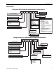
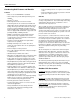
505430-BTG-A-0309 Typical Wiring Diagrams Air Conditioning Condensing Units Typical YH-07 Wiring Diagram Johnson Controls Unitary Products 77
505430-BTG-A-0309 Typical YH-10 / YH-12 Wiring Diagram 78 Johnson Controls Unitary Products
505430-BTG-A-0309 Typical YJ-10 / YJ-12 Wiring Diagram Johnson Controls Unitary Products 79
505430-BTG-A-0309 Typical YH-15 / YH-20 Wiring Diagram 80 Johnson Controls Unitary Products
505430-BTG-A-0309 Typical YJ-15 / YJ-20 Wiring Diagram Johnson Controls Unitary Products 81
505430-BTG-A-0309 Heat Pump Units Typical PH-07 Wiring Diagram 82 Johnson Controls Unitary Products
505430-BTG-A-0309 Typical PH-10 Wiring Diagram Johnson Controls Unitary Products 83
505430-BTG-A-0309 Typical PH-15 / PH-20 Wiring Diagram 84 Johnson Controls Unitary Products
505430-BTG-A-0309 Typical PJ-15 / PJ-20 Wiring Diagram Johnson Controls Unitary Products 85
505430-BTG-A-0309 Air Handling Units Typical NH-07 Wiring Diagram 86 Johnson Controls Unitary Products
505430-BTG-A-0309 Typical NH/NJ-10 Thru NH/NJ-20 Wiring Diagram Johnson Controls Unitary Products 87
505430-BTG-A-0309 Weights And Dimensions Corner Weights & Center of Gravity AC/HP Units Weight (lbs.) Shipping Operating 405 415 550 560 815 840 810 835 985 1010 980 1005 330 325 450 445 445 440 450 445 445 440 680 675 680 675 710 710 710 710 Model PH-07 PH-10 PH-15 PJ-15 PH-20 PJ-20 YH-07 YH-10 YJ-10 YH-12 YJ-12 YH-15 YJ-15 YH-20 YJ-20 Center of Gravity (in.) X Y 16 32.5 17.5 32.9 32.5 33 34 32.5 31 32.5 30.5 31.5 18.5 30.8 18 34 16.5 33.5 18 34 16.5 33.5 32.5 31.5 32.5 31.
505430-BTG-A-0309 RIGHT REAR B FRONT LEFT C REAR POWER DISCONNECT SWITCH 4X Ø 0.875 KNOCKOUT I 4X Ø 1.375 KNOCKOUT H F N G E D RIGHT FRONT M A 5.17 SYSTEM 2 FRONT L CONVENIENCE OUTLET 3.00 SYSTEM 1 L 3.38 K J P J K 4 PIPE APPLICATION ONLY - DETAIL REAR REAR LEFT Ø 1.500 THRU TYP 2.250 TYP O Unit Dimensions PH-07, PH-10, YH-07, YH/YJ-10, YH/YJ-12 Unit Dimensions MODEL PH-07 PH-10 YH-07 YH-10 YJ-10 YH-12 YJ-12 A 59.1 59.1 59.1 59.1 59.1 59.1 59.1 B 31.9 31.9 31.9 31.9 31.
505430-BTG-A-0309 REAR LEFT A RIGHT B FRONT Weatherproof cover shown in open position P Convenience Outlet C Control and Power wiring connections N D H S E I G R Power Disconnect Switch O M YH-15/-20 FRONT E K L Q F J YH/YJ-15 & YH/YJ-20 RIGHT D E1 D1 F1 F G1 G YJ-15/-20 FRONT (PIPING DETAIL) Unit Dimensions PH/PJ-15, PH/PJ-20, YH/YJ-15, YH/YJ-20 90 Johnson Controls Unitary Products
505430-BTG-A-0309 Unit Dimensions MODEL A B C D DI E EI F FI G GI H I J K L M N O P Q R S PH-15 59.1 64.1 44.5 13.8 N/A 13.4 N/A 20.2 N/A 23.9 N/A 15.0 12.5 11.4 8.4 2.4 3.9 22.0 2.9 4.9 7.1 4.8 14.7 PJ-15 59.1 64.1 44.5 13.7 10.1 13.3 9.7 10.3 18.8 24.2 22.0 15.0 12.5 11.4 8.4 2.1 3.6 22.0 2.9 4.9 7.1 4.8 14.7 PH-20 59.1 64.1 50.0 13.8 N/A 13.4 N/A 20.2 N/A 23.9 N/A 15.0 12.5 11.4 8.4 2.1 3.6 22.0 2.9 4.9 7.1 4.
505430-BTG-A-0309 Corner Weights & Center of Gravity NH/NJ Units Model NH-07 NH/NJ-10 NH/NJ-15 NH/NJ-20 NH-07 NH/NJ-10 NH/NJ-15 NH/NJ-20 Center of Gravity (in.) Shipping Operating X Y Weight (lbs.) Options Vertical Airflow Std. Mtr. and Drv. High Static Mtr. and Drv. Std. Mtr. and Drv. High Static Mtr. and Drv. Std. Mtr. and Drv. High Static Mtr. and Drv. Std. Mtr. and Drv. High Static Mtr. and Drv. Horizontal Airflow Std. Mtr. and Drv. High Static Mtr. and Drv. Std. Mtr. and Drv. High Static Mtr.
505430-BTG-A-0309 TOP VIEW 15.63 20.19 17.62 18.60 5.08 5.10 13.44 15.90 Ø 1.38 KNOCKOUT ELECTRIC HEAT CONNECTION Ø 1.38 KNOCKOUT ELECTRIC HEAT CONNECTION 4.68 4.68 18.44 18.44 TOP VIEW - BLOWER OUTLET NH-07 INDOOR TOP VIEW - BLOWER OUTLET NH/NJ-10 INDOOR FRONT AND SIDE VIEW 30.00 9.06 2.59 5.09 Ø 1.09 KNOCKOUT POWER ACCESS Ø 0.88 KNOCKOUT CONTROLS ACCESS 66.09 65.00 35.00 SYSTEM 2 7.43 6.44 5.54 4.16 FIELD PIPING CONNECTIONS 20.34 12.23 11.87 10.14 9.84 SYSTEM 1* 2.00 53.44 2.00 1.
505430-BTG-A-0309 TOP VIEW 21.58 26.46 3.44 18.91 Ø 1.38 KNOCKOUT ELECTRIC HEAT CONNECTION 10.23 24.71 TOP VIEW - BLOWER OUTLET NH/NJ-15 INDOOR FRONT AND SIDE VIEW 33.00 9.06 2.59 5.09 Ø 1.09 KNOCKOUT POWER ACCESS Ø 0.88 KNOCKOUT CONTROLS ACCESS 76.09 75.00 7.43 6.44 5.54 4.16 42.00 SYSTEM 2 FIELD PIPING CONNECTIONS 27.34 12.23 11.87 10.14 9.84 SYSTEM 1* 2.00 1.42 71.94 2.00 DRAIN CONNECTION 3/4 PVC PIPE CONNECTIONS 6.54 74.
505430-BTG-A-0309 TOP VIEW 54.65 18.63 18.63 25.37 23.62 4.94 Ø 1.38 KNOCKOUT ELECTRIC HEAT CONNECTION 5.11 15.90 Ø 1.38 KNOCKOUT ELECTRIC HEAT CONNECTION 5.56 23.47 TOP VIEW - BLOWER OUTLET NH/NJ-20 INDOOR FRONT AND SIDE VIEW 30.00 9.06 2.59 5.09 Ø 1.09 KNOCKOUT POWER ACCESS Ø 0.88 KNOCKOUT CONTROLS ACCESS 66.10 65.00 35.00 20.34 SYSTEM 2 7.43 6.44 5.54 4.16 12.23 11.87 10.14 9.84 2.00 45.97 2.00 95.94 SYSTEM 1* 2.00 1.42 98.
505430-BTG-A-0309 PIPING, ELECTRICAL AND DUCT OPENING CONNECTION SIZES MODEL NH-07 NH-10 NJ-10 NH-15 NJ-15 NH-20 NJ-20 SYSTEM DATA No. Refrigeration Circuits 1 1 2 1 2 1 2 1 1/8 1 3/8 1 1/8 1 5/8 1 1/8 1 5/8 1 3/8 Liquid Line OD (in.) 5/8 7/8 5/8 7/8 5/8 7/8 7/8 Power Wiring Knockout 1 1 1 1 1 1 1 Control Wiring Knockout 7/8 7/8 7/8 7/8 7/8 7/8 7/8 1 3/8 1 3/8 1 3/8 1 3/8 1 3/8 1 3/8 1 3/8 3/4 3/4 3/4 3/4 3/4 3/4 3/4 Suction Line OD (in.
505430-BTG-A-0309 Mounting The split air handling units can be applied in various horizontal positions. The Typical Suspension of AHU’s From Ceiling Figure shows recommended suspension rigging using properly sized all-thread and metal c-channel. All components to suspend an AHU must be field supplied. Please refer to the units total weight, center of gravity and corner weights. (Horizontal position) shown in the appropriate table for proper support sizing.
505430-BTG-A-0309 S1 G1 S2 G2 C S1 G1 S2 G2 C SINGLE STAGE THERMOSTAT Typical Field Wiring Diagram - NH-07 Unit 98 Johnson Controls Unitary Products
505430-BTG-A-0309 S1 G1 S2 G2 C S1 G1 S2 G2 C Typical Field Wiring Diagram - NH/NJ-10 Thru NH/NJ-20 Unit NOTE: On non NH/NJ Air Handler models isolation relays must be installed to avoid overloading on 75 VA transformer on the condensing unit.
Subject to change without notice. Printed in U.S.A. Copyright © 2009 by Johnson Controls, Inc. All rights reserved.