
User Guide
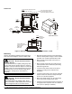
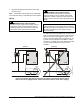
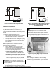
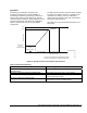


Table Of Contents

L1
M1
Capacitor
Main
Aux
R
C
S
Motor
24
VAC
L1
L2
P66
P66_WIRING
Figure 3: Permanent Split-Capacitor Motor
Connections to the P66 Fan Speed Control
L1
M1
Capacitor
Main
Aux
R
C
S
Motor
24
VAC
L1
L2
P66
P66_WIRING_OPT
Figure 4: Optional Wiring Diagram for Permanent
Split-Capacitor Motor Connections to the P66
Fan Speed Control
Setup and Adjustments
The P66 control’s throttling range is fixed and cannot
be adjusted. The operating range pressure is
adjustable within the control pressure range. See the
Technical Specifications table for P66 model pressure
ratings.
To adjust the operating range pressure:
1. Apply a reliable pressure gauge to the controlled
system to monitor the pressure adjustments.
2. Access the operating range adjustment screw for
the P66 pressure transducer through the opening
in the upper left-hand corner of the P66 control
base (Figure 5).
Note: On dual pressure models, access to the
second adjustment screw is located in the lower right-
hand corner of the control base.
3. Turn the adjustment screw 1/2 turn (or less)
clockwise to increase the operating range
pressure or 1/2 turn (or less) counterclockwise to
decrease the operating range pressure.
• Low Pressure Models (80 to 200 psig):
1/2 turn = approximately ± 9 psig (62 kPa)
• Medium Pressure Models (140 to 350 psig):
1/2 turn = approximately ± 18 psig (124 kPa)
• High Pressure Models (300 to 500 psig):
1/2 turn = approximately ± 35 psig (241 kPa)
IMPORTANT: Do not adjust the operating range
screw more than 1/2 turn before allowing the system
pressure to stabilize.
4. Check system pressure and repeat Step 3 until
the desired operating range pressure is attained.
!
CAUTION: Risk of Property Damage
Limit any adjustments to two full turns in either
direction. Over-adjustment may prohibit modulation
of the motor resulting in high head pressures. All
pressure adjustments should be verified with the use
of refrigerant pressure gauges.
Figure 5: Operating Range Adjustment Screw
Location
Checkout
Before leaving the installation, observe working
application for correct operation. See the Operation
section for a typical operational sequence.
4 P66 Series Electronic Fan Speed Controls Installation Instructions