
User Guide
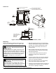
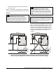
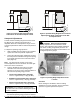
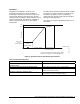


Table Of Contents

• Evacuate all tubing and lines before connecting
the P66 control.
Note: A Schrader® valve depressor is provided with
the female flare fitting on standard P66 control models.
Wiring
!
WARNING: Risk of Electric Shock
Disconnect power supply before making electrical
connections. Contact with components carrying
hazardous voltage can cause electric shock and
may result in severe personal injury or death.
!
WARNING: Risk of Electric Shock
Ground the P66 Series Electronic Fan Speed
Control according to local, national, and regional
regulations. Failure to ground the P66 control may
result in electric shock and severe personal injury or
death.
IMPORTANT: Use copper conductors only. Make all
wiring connections in accordance with the National
Electrical Code and local regulations. Do not exceed
the P66 Series Electronic Fan Speed Control’s
electrical ratings.
The P66 control must be supplied with 24 VAC (1 VA)
from an external transformer powered from the same
phase as the motor circuit (Figure 2, Figure 3, and
Figure 4). The low voltage input connections are 1/4
in. quick-connect terminals on the NEMA 1 models
and two 6 in. 22 AWG wires on the NEMA 3R models.
The line voltage connections are 10-32 screw
terminals.
Incorrect
Correct
L1
M1
Capacitor
Main
Aux
R
C
S
Motor
24
VAC
L1
L2
L3
P66
L1
M1
Capacitor
Main
Aux
R
C
S
Motor
24
VAC
L1
L2
L3
P66
P66_IN-PHASE_WIRRING
Figure 2: Permanent Split-Capacitor Motor Connections to the P66 Fan Speed Control
(The 24 VAC power supply must be connected in-phase with the motor power supply.)
P66 Series Electronic Fan Speed Controls Installation Instructions 3