
Specification Sheet
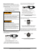

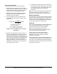

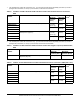


Table Of Contents

P499 Series Electronic Pressure Transducers Product/Technical Bulletin
5
Checking transducer operation
Before applying power, check all wiring connections.
After applying power, operate controlled equipment
under normal conditions and use a reliable set of
pressure gauges to verify that the transducer and the
associated control are operating properly.
0.5 VDC to 4.5 VDC ratiometric versions
The ratiometric versions of the P499 transducer
receive a constant 5 VDC (nominal) supply voltage and
vary the output signal voltage, based on the sensed
pressure. The output voltage varies from 10% to 90%
of the supply voltage, providing a 0.5 VDC to 4.5 VDC
(nominal) signal.
To verify that the transducer is working properly:
1. With the transducer in place and the controlled
system pressure stabilized, measure the pressure
at the transducer with an accurate and reliable
gauge. This is the measured pressure (P).
2. Determine the maximum (P
max) and minimum
(P
min) pressure values for the transducer’s
pressure range. (See Table 3, Table 4, or Table 5.)
3. Measure the voltage between Supply (red) wire
and Common (black) wire. (See Figure 3.) Use this
in Step 3 as the measured supply voltage, V
s.
4. Use the equation in Figure 7 to determine the
calculated output voltage for the ratiometric
transducer.
5. Using your multimeter, measure the DC voltage
between the transducer Output (white) wire and
Common (black) wire. (See Figure 3.) This is the
measured output voltage.
6. Compare the calculated output voltage (Step 4)
and the measured output voltage (Step 5). If the
measured output voltage differs greatly from the
calculated output voltage, replace the transducer.
Note: It is normal for the transducer reading to differ
somewhat from pressure gauge readings due to
voltmeter and gauge tolerances, and other factors.
0 VDC to 10 VDC versions
To verify that the transducer is working properly:
1. With the transducer in place and the controlled
system pressure stabilized, measure the pressure
at the transducer with an accurate and reliable
gauge. This is the measured pressure (P).
2. Determine the maximum (P
max) and minimum
(P
min) pressure values for the transducer’s
pressure range. (See Table 6.)
3. Use the equation in Figure 8 to determine the
calculated output voltage for the 0 VDC to 10 VDC
transducers.
4. Measure the voltage between the transducer
Output (white) wire and Common (black) wire with
a multimeter set to measure DC voltage. (See
Figure 3.) This is the measured output voltage.
5. Compare the calculated output voltage (Step 3)
and the measured output voltage (Step 4). If the
measured output voltage differs greatly from the
calculated output voltage, replace the transducer.
Note: It is normal for the transducer reading to differ
somewhat from pressure gauge readings due to
voltmeter and gauge tolerances, and other factors.
IMPORTANT: The P499 transducer is a precision
sensing device and testing accuracy is typically
beyond the capability of field diagnostic tools.
IMPORTANT: The 0.5 VDC to 4.5 VDC ratiometric
transducers are rated for 5.0 ±0.25 VDC, Safety
Extra-Low Voltage (SELV) or Class 2. Exceeding the
supply voltage rating can damage the transducer
and void any warranties.
P - (P )
min
V
= V 0.1 + 0.8 VDC
os
[]
( )
V = Calculated Output Voltage
V = Measured Supply Voltage
P = Measured Pressure
P = Maximum Pressure Value
P = Minimum Pressure Value
o
s
max
min
FIG:idl_ratiometric
Figure 7: Voltage calculation for 0.5 VDC to 4.5
VDC ratiometric transducers
V = Calculated Output Voltage
P = Measured Pressure
o
P = Maximum Pressure Value
P = Minimum Pressure Value
max
min
FIG:idl_10V
V
= 10 VDC
o
( )
P - (P )
min
Figure 8: Voltage calculation for 0 VDC to 10 VDC
transducers