
Install Instructions
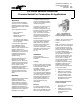
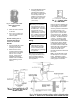
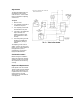
Table Of Contents

2
P32 Technical Bulletin
3. Place the metal connector
in the hole.
4. Use a 1/2 in. conduit lock
nut on the connector and
secure in place.
Remote mounting with “L”
bracket No. BKT182-2 or
channel “U” bracket No.
BKT229-1
1. Use the bracket as a guide
and drill or punch the
mounting screw holes.
2. Determine the correct
mounting bracket position
and secure it to the switch
with the 1/2 in. conduit
locknut. (There may be
installations where the
bracket must be installed
before fastening it to the
switch.)
3. Use FTG18A-600R remote
mounting probe kits for
remote sensing locations.
Run plastic or copper tubing
from the high and/or low
pressure connectors to the
sensing point. Use tubing
with at least .170 in. I.D.
(1/4 in. O.D.).
!
CAUTION: When turning
the fitting into the plastic
low pressure port, do not
overtighten and crack the
threaded boss. Turn fitting
in finger-tight, then an
additional 1 to 1-1/2 turns
(approximately 15 to 20 in.-
lbs.). Sealing compound or
tape is not required for the
plastic low pressure port.
Wiring
!
CAUTION: Disconnect
electrical power supply
before wiring switch into
circuit to avoid possible
electrical shock or damage
to equipment.
Make all wiring connections
using copper conductors only,
and in accordance with the
National Electrical Code and
local regulations.
Refer to job wiring diagrams for
proper hookup. If not available,
refer to diagrams in this sheet.
All wiring is made to terminals in
the wiring enclosure. The
terminals can be either screw
type or 1/4 in. x .032 in. male
quick connect type. The SPDT
models have color coded wiring
terminals. The Red terminal is
common. The Red to Yellow
circuit opens on a differential
pressure decrease and the Red
to Blue circuit closes. Models
are available with SPST open
low contact action and also with
SPST open high contact action.
The correct model must be
chosen so that all of the
terminals provided are wired into
the circuit.
Note
: Use the terminal screws
furnished (8-32 x 1/4 in. binder
head). Substitution of other
screws may cause problems in
making proper connections.
Fig. 2 -- Interior view of P32
Differential Pressure
Switch.