
Install Instructions
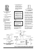
Table Of Contents

Installation Sheets Manual 121
Pressure Controls Section
Technical Bulletin P32
Issue Date 0485
© 1985 Johnson Controls, Inc.
1
Code No. LIT-121415
P32 Series Sensitive Differential
Pressure Switch For Combustion Air Applications
Application
The P32 differential pressure
switch is for use in combustion
applications where a proof of air
flow is needed for proper system
operation.
Typical applications include:
• Pulse combustion
appliances.
• Appliances with power
vented exhaust.
• Any appliance that requires
proof of flow before initiating
burner operation.
In all combustion applications,
the P32
must
be used in
conjunction with a backup
device to either check the P32’s
operation each time the
appliance cycles, or to operate
independently of the P32 to de-
energize the burner circuit
should improper appliance
operation occur.
All Series P32 switches are
designed for use
only
as
operating controls. Where an
operating control failure would
result in personal injury and/or
loss of property, it is the
responsibility of the installer to
add devices (safety, limit
controls) that protect against, or
systems (alarm, supervisory
systems) that warn of control
failure.
Operation
This differential pressure switch
senses a change in the
differential pressure (either
velocity pressure or pressure
drop across a fixed restriction)
as air flow in the flue changes.
This differential pressure, as
sensed by the two sensing ports,
is applied to the two sides of a
diaphragm in the switch.
The spring loaded diaphragm
moves and actuates the switch
when the air pressure difference
reaches the set point.
This switch can also be used to
detect small positive gage
pressure by using only the high
pressure connection and leaving
the low pressure connector
open, or to detect a vacuum by
using only the low pressure
connection and leaving the high
pressure connector open to
ambient pressure.
The P32 should be used only in
conjunction with a redundant
safety device such as a spill
switch and self-checking relay
circuit, and only on open
combustion equipment. Closed
combustion units require a self-
checking relay circuit. (See
Fig. 6.)
Installation
Follow equipment
manufacturer’s instructions, if
available.
Locating
Select a location near the blower
or flue where vibration is minimal
and the terminal screws are
accessible. Ambient
temperature should be within the
range of -40 to 165°F (-40 to
74°C) to avoid physical damage
to the pressure switch. Because
the factory setting of the P32 is
made at room temperature, the
P32 should be mounted in a
location with temperatures as
close as possible to room
temperature.
Mounting
The P32 is normally mounted
with the diaphragm in a vertical
plane. It may be fastened to any
flat surface which has minimal
vibration. Do not mount the P32
directly to the flue or any hot
surface.
Note
: If the switch is mounted in
a position other than the position
in which it was factory set, the
setting will change. If the switch
is factory set with the diaphragm
in a vertical position but is
mounted in a horizontal position
with the steel housing (high
pressure connector) down, the
set point will increase by about
0.07 in. W.C. (.017 kPa). If
mounted with the steel housing
up, the switch may be
inoperative at minimum setting.
Adjustable models can be re-
adjusted for this mounting
position and minimum set point
on the job as follows:
1. Mount the switch securely.
2. Make sure no pressure is
applied to either connector.
3. Turn the adjusting screw
clockwise until the switch
operates and then at least
an additional 1/3 turn.
Panel mounting with the high
pressure connector
1. Cut or drill a 7/8 in. (22 mm)
diameter hole.
2. Install tubing in the 1/8 in.
Female NPT high pressure
(metal) connector, if
required.
Fig. 1 -- P32 Differential
Pressure Switch with “U”
mounting bracket assembled.