
User Guide
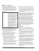
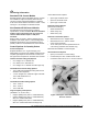
Table Of Contents

4 P
—P100 Series Encapsulated Pressure Controls Product/Technical Bulletin
M
ounting
The compact size and lightweight construction of the
P100 series controls allows mounting the control
directly to the refrigeration piping or almost any other
convenient pressure tap point on the system. Observe
the following guidelines when installing the
P100 controls.
IMPORTANT: If these controls are installed on
equipment containing hazardous
or regulated materials, such as
refrigerants or lubricants, the
installer and user should observe
all regulations governing the
handling and containment of
those materials.
IMPORTANT: Pressure tap points should be
located on the top side of the
refrigerant lines. This reduces the
possibility of sediment
accumulating in the control.
Do Not Over Tighten Flare Nuts on Pressure
Connection Fittings.
Over tightening flare
connections may damage the threads on the flare nuts
or flare connectors, and result in refrigerant leaks. Do
not exceed 9 lb
.
ft [12 N
.
m] of torque when tightening
brass flare connections.
Avoid Severe Pressure Pulsation
on High-Side
Pressure Connections.
Install P100 controls on
pressure tap points away from the compressor
discharge, to minimize the affects of pressure
pulsation from reciprocating compressors.
Note: Refer to
Brazing a P100 with a Thermal
Isolation Fitting Application Note (LIT-125512)
for guidelines on mounting controls with TIF
pressure connections.
W
iring
P100 Encapsulated Pressure Controls are available
with several switch options and electrical ratings.
Check the label on the control body for model number.
Refer to the following guidelines and diagrams when
wiring the P100 controls.
!
WARNING:
Risk of
Electrical Shock.
Disconnect power supply before
making electrical connections to
avoid possible electrical shock or
equipment damage.
IMPORTANT: Make all wiring connections in
accordance with the National
Electrical Code and all local
regulations. Use copper
conductors only. Do not exceed
the control’s electrical rating.
L1
L2
Load
Open-high switch action:
opens on pressure rise
L1
L2
Load
Open-low switch action:
opens on pressure drop
Figure 3: Wiring Diagrams for P100 Control Models
with an SPST Switch
SPDT Switch Position at Low Pressure
(Open 1 to 3 and Close 1 to 2 on Rise)
2
1
3
1/4 in. Male Spade
Terminal Locations
1 (C )
2
(N.O.)
3
(N.C.)
L1
L2
Load
Alarm
Figure 4: Wiring Diagram and Terminal Locations
for P100E Control Models with an SPDT Switch
IMPORTANT: After mounting and wiring
control, attach a reliable set of
gauges to the controlled
equipment and operate the
equipment (at least) three cycles
at the pressures necessary to
verify control setpoints and
proper operation.
Do not exceed manufacturers’
recommended pressure ratings
for the controlled equipment or
any of its components when
operating the controlled
equipment.
R
epairs and Replacement
Field repairs to the P100 pressure controls must not
be made. For a replacement control, contact an
authorized Johnson Controls Sales Representative or
Distributor, or Refrigeration Application Engineering at
414-524-5535.