
Product Overview


8 P-3800 Product Bulletin
If desired, check the
minimum and maximum
flow set point settings by
disconnecting the
thermostat air line and
repeating Steps 9
through 11.
12. Return the room thermostat
(or other master controller)
dial setting to the desired
temperature.
13. Remove the magnehelic
gage or manometer that is
teed in the high and low
pressure pickup lines and
cap the open end of each
tee using F-1000 Series
Sealing Caps (ordered
separately).
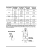
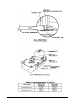
14. Mark the self-adhesive
identification sticker (see
Fig. 9) included with the
P-3800 as indicated. Apply
the sticker to an available
surface near the controller
for future identification.
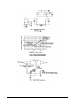
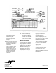
Repair Information
To avoid entire unit changeout
and recalibration should an air
supply system oil contamination
problem arise, the P-3800 is
equipped with a replaceable
filter/orifice assembly (see
Fig. 8). This filter/orifice
assembly is also available
separately as a repair part;
order P-3800-600.
In heavily contaminated air
supply systems, it is
recommended that an
A-4000-137 Oil Removal Filter
(ordered separately) be used
inline before the P-3800, to slow
the need for replacing the
P-3800-600 Filter/Orifice
Assembly. Contact the local
Johnson Controls branch office
for advice on how to alleviate
this contamination in the air
supply system.
Other than the filter/orifice
assembly, field repairs to the
P-3800 Reset Volume Controller
must not be made. For a
replacement P-3800, contact the
nearest Johnson Controls
branch office.
Controls Group
507 E. Michigan Street
P.O. Box 423 Printed in U.S.A.
Milwaukee, WI 53202