
Product Overview


P-3800 Product Bulletin 7
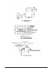
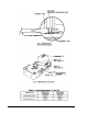
Air Line Connections
7. Referring to the air
connection identification
label attached to the surface
of the P-3800 (see Fig. 6)
and the notations made in
Step 1, connect all air lines
EXCEPT THE
THERMOSTAT AIR LINE to
the appropriate barbed air
connections on the P-3800
(see Fig. 8).
Note: To ensure leak-free
connections, cut off 1/2 in.
(13 mm) of the old tubing
ends before making the air
line connections. Also, the
P-3800 requires 3/8 in. O.D.
polytubing for the high and
low pressure pickups;
straight couplers
(F-300 Series, ordered
separately) may be required
to connect to the existing
pressure pickup lines.
Connect the supply air line
to the supply "S" connection
and the output air line to the
output "O" connection.
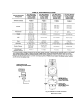
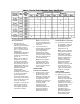
In addition, connect the high
and low pressure pickup
lines to inputs "I", and "II"
for the specific application,
as indicated in Table 3.
Note: A later step covers
connecting the thermostat
air line to the thermostat "T"
connection.
8. Locate the two sets of
mounting tabs on both sides
of the P-3800 body (see
Fig. 6) and install the
P-3800 into the existing
mounting bracket retained
in Step 2, until the mounting
tabs "click" into the slots on
the mounting bracket.
Note: After the P-3800 is
installed in the existing
mounting bracket, check
that there are no kinks in
any of the air lines leading
to the controller.
BRASS SCREW
Flow Set Point Adjustment
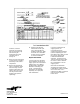
9. Referring to Fig. 6, adjust
the brass screw to the
desired set point (either
maximum or minimum flow
as identified in Table 4) to
correspond to the value
indicated on the VAV box or
the system drawing. Turn
the screw in small
increments until the
magnehelic gage or
manometer (teed into the
high and low pressure
pickup lines) reads the
desired flow set point.
Thermostat Air Line Connection
10. Connect the thermostat air
line (identified in Step 1) to
the thermostat "T" barbed
air connection on the
P-3800 (see Fig. 8).
Note: This air line (whether
coming from a thermostat,
reversing relay, or some
other master controller)
must be furnishing at least
15 PSIG (105 kPa) to the
P-3800 "T" barbed air
connection; temporarily
adjust the thermostat to
provide this required
15 PSIG. To ensure a leak-
free connection, cut off
1/2 in. (13 mm) of the old
tubing end before making
the air line connection.
STEEL SCREW
Flow Set Point Adjustment
11. Referring to Fig. 6, adjust
the steel screw to the
desired set point (either
maximum or minimum flow
as identified in Table 4) to
correspond to the value
indicated on the VAV box or
the system drawing. Turn
the screw in small
increments until the
magnehelic gage or
manometer (teed into the
high and low pressure
pickup lines) reads the
desired flow set point.