
Product Overview
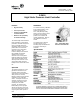
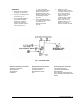
Table Of Contents

P-3610 Product Bulletin 3
Calibration
1. Apply 20 PSIG (140 kPa) to
the supply “S” connection.
2. Hook up a test divider circuit
as shown in Fig. 4.
3. Close adjustable restrictor
#1 and open adjustable
restrictor #2. Adjust the
S-224 gradual switch to
provide a 9 PSIG output as
read on test gage #1.
4. Open adjustable
restrictor #1 slowly until the
P-3610 inlet pressure is
approximately 90% of the
desired set point (as read on
the differential pressure
gage #3).
5. Close adjustable restrictor
#2 until the desired set point
is indicated on the
differential pressure
gage #3.
6. Adjust the P-3610
adjustment dial to provide
the output pressure (as read
on test gage #2) which
equals the upper range
pressure of the fan
modulation device spring
range. Example: If the
spring range of the fan
modulation device is 3 to
15 PSIG, the desired
pressure would be 15 PSIG.
European Single Point of Contact:
NA/SA Single Point of Contact:
APAC Single Point of Contact:
JOHNSON CONTROLS
WESTENDHOF 3
45143 ESSEN
GERMANY
JOHNSON CONTROLS
507 E MICHIGAN ST
MILWAUKEE WI 53202
USA
JOHNSON CONTROLS
C/O CONTROLS PRODUCT
MANAGEMENT
NO. 22 BLOCK D NEW DISTRICT
WUXI JIANGSU PROVINCE 214142
CHINA