
Install Instructions


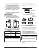

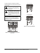


Table Of Contents
- Applications
- Installation
- Accessories
- Mounting
- Wiring
- Setup and Adjustments
- Direction of Action
- Mode Selector Switch/RA and DA Function
- CAL Function
- Setting the Zero (Y1) and Span Voltages (Y2-Y1)
- Setting the Zero (Y1) Voltage
- Setting the Span (Y2 - Y1) Voltage
- Inspecting the Zero (Y1) and Span (Y2-Y1) Voltages
- Inspecting the Zero (Y1) Voltage Setting
- Inspecting the Span (Y2-Y1) Voltage Setting
- Tandem Operation: HGx Master with GGx Slaves
- Energizing Master (DHF1) and Slave (DFM1) Actuator(s)
- Resetting Factory Defaults for an HGx Actuator
- Auxiliary Switches (HGC Models Only)
- Repairs and Replacement
- Technical Specifications

M9220-HGx-3 Proportional Electric Spring Return Actuators Installation Instructions 9
CAL Function
The Calibrate (CAL) function enables the actuator to
redefine the selected control input range proportionally
across a reduced rotation range. The actuator stores
the reduced rotation range in nonvolatile memory
(retains data when power is lost or removed).
The DC 0 to 10 V input signal corresponds to -5 to 90°
rotation. If the rotation range is reduced, the end-stop is
reached with a reduced input signal. For example, if a
DC 0 to 10 V input signal is selected and the rotation
range is limited to 75°, the end-stop is reached at
DC 8.3 V. After calibration, the end-stop is reached at
DC 10 V.
To calibrate the control input range, proceed as follows:
1. With power off, move the mode selection switch to
the CAL position (Figure 14). Then, energize the
actuator. The actuator automatically rotates until
the end-stops are found and proportionally
reconfigures the control input range to the reduced
rotation range.
2. Return the mode selection switch to the desired
selection (example: DA).
Note: During normal operation, if the actuator
stroke increases due to seal or seat wear, the input
is redefined to the increased rotation range in
approximately 0.5° increments.
3. If the actuator mounting position is changed or if
the linkage is adjusted, repeat Steps 1 and 2 to
reinitiate the CAL function.
Note: To repeat calibration with power applied,
move the mode selection switch out of the CAL
position for at least 2 seconds before returning it to
the CAL position. Auto calibration begins
5 seconds after you return it to the CAL position.
Setting the Zero (Y1) and Span Voltages
(Y2-Y1)
The command voltage value for a minimum hub angle
(the zero setting) and the change in command value
required to travel the total hub angle (the span) are
adjustable (Figure 14). These settings are with respect
to the minimum hub angle and the total travel distance
defined during the CAL function. If the actuator is
powered on, the Span voltage can be set right after the
Zero voltage is set without first powering down the
actuator.
Setting the Zero (Y1) Voltage
To set the Zero (Y1) voltage:
1. With power off, set the mode selector switch
(Figure 14) to the zero (Y1) position.
2. Energize the actuator.
3. Adjust the voltage switch (Figure 15) to the desired
zero voltage as displayed on the printed 0-10
scale. To inspect the exact setting voltage, attach a
voltmeter between the feedback wires (orange [+]
and black [common]).
4. Set the mode selector switch to the RA or DA
position. The zero voltage setting is now stored.
Setting the Span (Y2 - Y1) Voltage
To set the Span (Y2 - Y1) voltage:
1. With power off, set the mode selection switch to the
span (Y2-Y1) position.
2. Energize the actuator.
3. Adjust the voltage potentiometer switch to the
desired span voltage as displayed on the printed
0-10 scale. To inspect the exact setting voltage,
attach a voltmeter to the feedback wire.
4. Set the mode selection switch to the RA or DA
position. The span voltage setting is now stored.
Figure 14: CAL Operation Setup (highlighted)
selmode
Side A of Actuator Side B of Actuator
Y
Y1
Y2-Y1
+
+
CALCAL
Y
Y1
Y2-Y1
+
+
RA
DA
RA
DA
CAL, Zero Y, Span Y1, Span Y2-Y1
CAL and Zero/Span Selector
Figure 15: Potentiometer Adjustment for Setting
Span and Zero Voltage
adjsw
Side A of Actuator Side B of Actuator
10 0
5
7
3
MASTER
NORMAL
Y1
Y2-Y1
010
5
3
7
NORMAL
MASTER
Y1
Y2-Y1