
Install Instructions


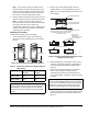

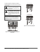


Table Of Contents
- Applications
- Installation
- Accessories
- Mounting
- Wiring
- Setup and Adjustments
- Direction of Action
- Mode Selector Switch/RA and DA Function
- CAL Function
- Setting the Zero (Y1) and Span Voltages (Y2-Y1)
- Setting the Zero (Y1) Voltage
- Setting the Span (Y2 - Y1) Voltage
- Inspecting the Zero (Y1) and Span (Y2-Y1) Voltages
- Inspecting the Zero (Y1) Voltage Setting
- Inspecting the Span (Y2-Y1) Voltage Setting
- Tandem Operation: HGx Master with GGx Slaves
- Energizing Master (DHF1) and Slave (DFM1) Actuator(s)
- Resetting Factory Defaults for an HGx Actuator
- Auxiliary Switches (HGC Models Only)
- Repairs and Replacement
- Technical Specifications

M9220-HGx-3 Proportional Electric Spring Return Actuators Installation Instructions8
Setup and Adjustments
Direction of Action
The M9220-HGx-3 Proportional Electric Spring Return
Actuators are factory set for Direct Acting (DA)
operation. In DA mode, applying an increasing input
signal to the control input drives the actuator away from
the spring return position. Reverse Acting (RA)
operation is also available. In RA mode, applying an
increasing input signal to the control input drives the
actuator toward the spring return position. Figure 13
and Figure 12 indicate how the drive direction for the
actuator depends on the spring return direction and the
position of the mode selection switch.
Mode Selector Switch/RA and DA Function
The M9220-HGx-3 Proportional Electric Spring Return
Actuators are factory set at DA, 0 to 10 VDC control
input.
12
34
~
Y
COM
U
BLK
RED
GRY
ORN
+
+
Override to MIN position
AC
24 V
DC 0(2)...10 V
DC 0(2)...10 V
A
A Open = MIN Position
A Closed = Normal Operation
12
34
~
Y
COM
U
BLK
RED
GRY
ORN
+
+
Override to MAX position
AC
24 V
DC 0(2)...10 V
DC 0(2)...10 V
C
B Closed = MAX Position
C Closed = Normal Operation
B
1
2
3
4
~
COM
U
BLK
RED
GRY
ORN
+
+
Override to
MIN, MID, MAX positions
0(4)...20 mA Control with
External Resistor
AC
24 V
A
0(4)...20 mA
500 / 0.25 W
B
C
1
2
3
4
~
COM
U
BLK
RED GRY
ORN
+
+
Override to
MIN, MID, MAX positions
0(2)...10 V Control
AC
24 V
A
B
C
DC
0(2)...10 V
Y
F
U
N
C
T
I
O
N
A
B
C
0% ( MIN )
50% ( MID )
100% ( MAX )
NORMAL
F
U
N
C
T
I
O
N
A
B
C
0% ( MIN
︶
50% ( MID )
100% ( MAX )
NORMAL
Y
Ω
FIG:M92 0xGGx_wir
Figure 11: M9220-HGx-3 Control Wiring Diagram
(Overrides)
Figure 12: Nominal Feedback Signal Relative to
Rotation Position
A
B
Control Inputs
CCW Face
of Actuator
CW Face
of Actuator
DA
RA
DARA
Mode Selection
Switch Setting
Increasing Signal
Decreasing Signal
F
I
G
:
D
R
V
P
O
S
Rotation Position
0-10V
Direct
Acting
Reverse
Acting
0-10V
0° is the spring return position.
*
FeedbackDirection
0.0V 1.7V 3.3V 5.0V 6.7V 8.3V 10.0V
10.0V 8.3V 6.7V 5.0V 3.3V 1.7V 0.0V
2
-10V
2.0V 3.3V 4.7V 6.0V 7.3V 8.7V 10.0V
2-10V
10.0V 8.7V 7.3V 6.0V 4.7V 3.3V 2.0V
Figure 13: Mode Selector (highlighted)
set
r
un
Side A of Actuato
r
Side B of Actuator
Y
Y1
Y2-Y1
+
+
CALCAL
Y
Y1
Y2-Y1
+
+
RA
DA
RA
DA
Reverse Acting (RA) or Direct Acting (DA)
Mode Selector