
Install Instructions


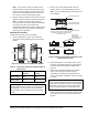

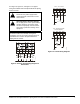


Table Of Contents
- Applications
- Installation
- Accessories
- Mounting
- Wiring
- Setup and Adjustments
- Direction of Action
- Mode Selector Switch/RA and DA Function
- CAL Function
- Setting the Zero (Y1) and Span Voltages (Y2-Y1)
- Setting the Zero (Y1) Voltage
- Setting the Span (Y2 - Y1) Voltage
- Inspecting the Zero (Y1) and Span (Y2-Y1) Voltages
- Inspecting the Zero (Y1) Voltage Setting
- Inspecting the Span (Y2-Y1) Voltage Setting
- Tandem Operation: HGx Master with GGx Slaves
- Energizing Master (DHF1) and Slave (DFM1) Actuator(s)
- Resetting Factory Defaults for an HGx Actuator
- Auxiliary Switches (HGC Models Only)
- Repairs and Replacement
- Technical Specifications

M9220-HGx-3 Proportional Electric Spring Return Actuators Installation Instructions 5
Note: The actuator requires 27 rotations of the
manual override crank from the fully spring return
position to fully reposition the actuator hub. At the
end of travel, the rotational resistance increases;
do not force the actuator hub past this point.
4. Rotate the manual override crank a half turn in the
opposite direction to lock the actuator hub in place.
Note: To unlock the actuator hub, rotate the
manual override crank in the direction indicated by
the arrow on the label. The actuator hub
automatically unlocks when power is applied to the
actuator, and returns the actuator to normal drive
and spring return operation.
Mounting the Actuator
To mount the actuator, proceed as follows:
1. See the dimensions in Figure 5 and Table 2 to
ensure the correct positioning of the anti-rotation
bracket.
2. Bend or cut the anti-rotation bracket to fit the
damper frame or duct as illustrated in Figure 6.
Note: The anti-rotation bracket can be bent to fit a
round damper.
3. Drill mounting holes in the damper frame or duct
using the anti-rotation bracket as a guide (based
on the measurements obtained in Table 2 and
Figure 5).
4. Secure the anti-rotation bracket to the damper
frame or duct using the two M3 x 9.5 mm
self-drilling sheet metal screws provided and a
1/4 in. (6 mm) blade screwdriver or 5/16 in. (8 mm)
nut driver.
5. Slide the actuator onto the damper shaft, and
position the tab of the anti-rotation bracket into the
slot at the bottom of the actuator as illustrated in
Figure 6.
Table 2: Dimensions from Anti-rotation Bracket to
Shaft Center
Shaft Diameter Dimension A,
in. (mm)
Dimension B,
in. (mm)
1/2 to 9/16 in.
(12to14mm)
8-9/32
(210)
7
(178)
5/8 to 3/4 in.
(16to19mm)
8-5/32
(207)
6-29/32
(175)
IMPORTANT: The tab on the anti-rotation bracket
must fit midpoint in the actuator slot. Positioning the
tab midpoint in the slot prevents actuator binding
and premature wear, and makes actuator removal
easier.
Figure 5: Positioning the Anti-Rotation Bracket
A
Dimension
B
A
FIG:brpos
Dimension
A
IMPORTANT: Do not overtighten the mounting
screws to avoid stripping the threads. Be certain that
the tab on the anti-rotation bracket remains properly
positioned in the slot on the actuator, and that the
actuator remains parallel to the mounting surface.
Figure 6: Fitting the Anti-Rotation Bracket on the
Damper Frame or Duct
Anti-rotation Bracket
Anti-rotation Bracket
Slot for Mounting the
Anti-rotation Bracket
Anti-rotation Bracket
Damper Frame
FIG:brfit
Actuator Shown with Anti-rotation Bracket
Assembled to Both the Top and Bottom
Anti-rotation Slots
M3 x 9.5 mm
Self-Drilling
Sheet Metal Screws
(Two Locations)