
Install Instructions
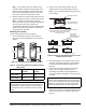

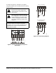


Table Of Contents
- Applications
- Installation
- Accessories
- Mounting
- Wiring
- Setup and Adjustments
- Direction of Action
- Mode Selector Switch/RA and DA Function
- CAL Function
- Setting the Zero (Y1) and Span Voltages (Y2-Y1)
- Setting the Zero (Y1) Voltage
- Setting the Span (Y2 - Y1) Voltage
- Inspecting the Zero (Y1) and Span (Y2-Y1) Voltages
- Inspecting the Zero (Y1) Voltage Setting
- Inspecting the Span (Y2-Y1) Voltage Setting
- Tandem Operation: HGx Master with GGx Slaves
- Energizing Master (DHF1) and Slave (DFM1) Actuator(s)
- Resetting Factory Defaults for an HGx Actuator
- Auxiliary Switches (HGC Models Only)
- Repairs and Replacement
- Technical Specifications

M9220-HGx-3 Proportional Electric Spring Return Actuators Installation Instructions12
Auxiliary Switches (HGC Models Only)
The HGC models include two integral auxiliary
switches with a switch adjuster accessible on either
face of the actuator (as illustrated in Figure 2 and
Figure 3). The nominal factory setting for Auxiliary
Switch No. 1 is 11° closing, and the nominal factory
setting for Auxiliary Switch No. 2 is 81° opening
(relative to a 0 to 90° rotation range). See the Technical
Specifications table for the auxiliary switch ratings.
The switch point of Auxiliary Switch No. 1 is fixed. The
switch point of Auxiliary Switch No. 2 is independently
and continuously adjustable from 25 to 95°. See
Figure 18 and use the method in the following example
for the most accurate positioning of Auxiliary Switch
No. 2.
To change the switch point of Auxiliary Switch No. 2,
proceed as follows:
1. Position the actuator in the full spring return
position.
Note: Auxiliary Switch No. 2 is factory set to trip
when the actuator reaches the 81° position.
2. Rotate the switch adjuster until it points to the
desired switch point.
3. Connect Auxiliary Switch No. 2 to a power source
or an ohmmeter, and apply power to the actuator.
The actuator moves to the fully open position and
holds while power is applied.
4. Observe the switch point. If required, repeat
Steps 2 and 3.
Repairs and Replacement
A number of replacement parts are available; see
Table 1 for more details. If the M9220-HGx-3 Series
Proportional Electric Spring Return Actuator fails to
operate within its specifications, replace the unit. For a
replacement electric actuator, contact the nearest
Johnson Controls representative.
Technical Specifications
!
WARNING: Risk of Electric Shock.
Disconnect or isolate all power supplies
before making electrical connections.
More than one disconnect or isolation
may be required to completely
de-energize equipment. Contact with
components carrying hazardous voltage
can cause electric shock and may result
in severe personal injury or death.
Figure 18: Switch Point Settings
A
FIG:s
wpnt
Switch
Adjuster
M9220-HGx Proportional Electric Spring Return Actuators (Part 1 of 3)
Power Requirements AC 24 V (AC 19.2 to 30 V) at 50/60 Hz: Class 2 (North America) or SELV
(Europe), 15.5 VA Running, 7.7 VA Holding Position;
DC 24 V (DC21.6 to 26.4V): Class 2 (North America) or SELV
(Europe), 6.7 W Running, 2.9 W Holding Position
Transformer Sizing Requirements 20 VA Minimum per Actuator
Input Signal/Adjustments Factory Set DC 0 to 10 V, CW Rotation with Signal Increase;
Selectable DC 0 to 10 V or 0 to 20 mA with Field Furnished 500 Ohm,
0.25 W Minimum Resistor;
Start Point Programmable DC 0 to 10 V;
Span Programmable DC 2 to 10 V;
Switch Selectable Direct or Reverse Action with Signal Increase
Control Input Impedance Voltage Input: 100,000 Ohms;
Current Input: 500 Ohms with Field Furnished 500 Ohm Resistor
Feedback Signal 0 to 10 VDC for Desired Rotation Range up to 90°;
Corresponds to Rotation Limits, 1 mA maximum
Auxiliary Switch Rating HGC Models Two Single-Pole, Double-Throw (SPDT), Double-Insulated Switches with
Gold Flash Contacts:
24 VAC, 50 VA Pilot Duty;
120 VAC, 5.8 A Resistive, 1/4 hp, 275 VA Pilot Duty;
240 VAC, 5.0 A Resistive, 1/4 hp, 275 VA Pilot Duty