
Install Instructions


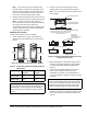

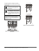


Table Of Contents
- Applications
- Installation
- Accessories
- Mounting
- Wiring
- Setup and Adjustments
- Direction of Action
- Mode Selector Switch/RA and DA Function
- CAL Function
- Setting the Zero (Y1) and Span Voltages (Y2-Y1)
- Setting the Zero (Y1) Voltage
- Setting the Span (Y2 - Y1) Voltage
- Inspecting the Zero (Y1) and Span (Y2-Y1) Voltages
- Inspecting the Zero (Y1) Voltage Setting
- Inspecting the Span (Y2-Y1) Voltage Setting
- Tandem Operation: HGx Master with GGx Slaves
- Energizing Master (DHF1) and Slave (DFM1) Actuator(s)
- Resetting Factory Defaults for an HGx Actuator
- Auxiliary Switches (HGC Models Only)
- Repairs and Replacement
- Technical Specifications

M9220-HGx-3 Proportional Electric Spring Return Actuators Installation Instructions10
Inspecting the Zero (Y1) and
Span (Y2-Y1) Voltages
When the actuator is powered up, moving the switch to
the zero or span position does not change the saved
zero or span setting. Instead, this causes the exact Y1,
Y2-Y1 voltage values to be displayed on the feedback
(orange) wire.
Inspecting the Zero (Y1) Voltage Setting
To inspect the Zero (Y1) voltage setting:
1. Energize the actuator and set the mode selection
switch to the zero (Y1) position. Attach a voltmeter
between the feedback wires (orange [+] and black
[common]). Read the voltage setting.
2. Set the mode selection switch to the RA or DA
position.
Inspecting the Span (Y2-Y1) Voltage Setting
To inspect the Span (Y2 - Y1) voltage setting:
1. Energize the actuator and set the mode selection
switch to the span position. Attach a voltmeter
between the feedback wires (orange [+] and black
[common]). Read the voltage setting.
2. Set the mode selection switch to the RA or DA
position.
Tandem Operation: HGx Master with
GGx Slaves
Note: The zero and span voltage settings must be
completed before configuring actuators for tandem
operation. If changes are required after the actuators
are configured for tandem operation, remove power
from the actuators and disconnect the master HGx
feedback wire from the slave GGx actuator wire. This
prevents the slave actuator from responding to setup
values on the feedback wire. See Setting the Zero (Y1)
and Span Voltages (Y2-Y1).
The tandem configuration (Figure 16 and Figure 17)
provides twice (with two actuators) or triple (with three
actuators) the running and spring return torque of a
single actuator (354 lb·in [40 N·m], 531 lb·in
[60 N·m]). One GGx actuator may be mounted in
tandem with one HGx model using the M9000-158
Tandem Mounting Kit. To mount a third actuator,
user-configured bracketing is required.
Follow these guidelines for tandem operation:
• One M9220-HGx-3 actuator and one or two
M9220-GGx-3 actuators may be operated in
tandem on the same shaft. If mounting two
actuators, see Figure 16; for three actuators, see
Figure 17.
• Each actuator requires separate 24 V power. When
two or more actuators connected in tandem share
a common power source, the total maximum power
draw is actually 1.5 times the normal running
current for each actuator. (Total Power = Number of
Actuators x Running Power x 1.5)
• The HGx actuator must be configured as the
master by setting the adjustment potentiometer to
the master position.
• The other GGx actuator(s) must be configured as
slave(s), by setting the Mode Selector switch to the
slave position.
• The master accepts DC 0 to 20 V command
signals as programmed for zero and span
operation.
• The master and slave(s) must have matching
RA/DA settings.
• The master and slave(s) must spring return in the
same direction.
• Once tandem-operating actuators are mounted to
a common or linked shaft, manual override is no
longer an available function.
The feedback wire of the master (orange) is connected
to the command wire(s) of the slave(s)(gray). As the
master moves in response to position commands, the
master sets its feedback wire to 0 V if moving
clockwise, 5 V if holding, or 10 V if moving
counterclockwise.
Each slave actuator must have its function switch set
on the slave setting. Its gray command wire must be
connected to the master’s orange feedback wire.
Figure 16: Tandem Connection
t
a
n
d
e
m
1
Master
(HGx)
DC 0...20V Control with Tandem Connection
Slave
(GGx only)
1
2
34
Y
BLK
RED
GRY
ORN
0(2)...10 VDC
+
1
2
34
U
BLK
RED
GRY
ORN
+
24 V
AC/DC
~
(+)
0...20 VDC
COM
+