
Install Instructions
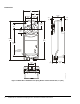
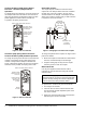
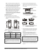
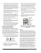
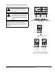
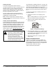
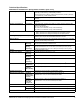
Table Of Contents

M9220-Bxx-3 On/Off Electric Spring Return Actuators Installation Instructions6
6. Rotate the damper blade(s) to the desired position
if the power is lost. To ensure a tight seal, insert the
manual override crank and turn it in the direction
indicated by the arrow on the label 5 turns; the
position indicator should be near the 0° position on
the scale. Quickly rotate the manual override crank
a half turn in the opposite direction to temporarily
lock the actuator hub in place.
7. Evenly hand tighten each clamp nut onto the
U-bolt, keeping the actuator flat. Secure the U-bolt
to the damper shaft and tighten to a torque of 100
to 125 lb⋅in (11 to 14 N⋅m).
8. To release the spring, turn the manual override
crank in the direction indicated on the label; the
actuator spring returns to its starting position. If this
step is omitted, the spring releases automatically
when power is applied to the actuator.
9. Remove the manual override crank and store it in
an unused mounting hole.
10. Apply power long enough for the actuator to travel
a full stroke, and verify that the actuator rotates
freely throughout the range.
Note: If electric power is not available, complete
this verification by reinserting the manual override
crank and turning it in the direction indicated to
rotate the coupler to the fully open position.
Rotation Range Using Optional
M9220-603 Adjustable Stop Kit
The actuator is factory set for 90° rotation, and its
rotation range is limited in 5° increments to a minimum
of 30°. Stroke limiting stops are attached in the field to
the shaft coupler side of the actuator to reduce the
rotation range. Attaching a stroke limiting stop in the
furthest mounting position reduces the rotation range of
the actuator by 5°. Each progressive mounting position
reduces the rotation range an additional 5°.
1. Check that the damper blade is visually accessible
or that its position is permanently marked on the
end of the damper shaft as illustrated in Figure 7.
2. Determine the desired rotation range. If a 65 to
90° rotation range is desired, add one stroke
limiting stop. If a 35 to 60° rotation range is desired,
add two stroke limiting stops.
Note: If two stroke limiting stops are applied, use
the manual override crank to position and lock the
actuator in a mid-stroke position to gain access to
both stroke limiting stop mounting positions.
3. Mount the stroke limiting stop(s) in the desired
position using the two M4 x 10 mm self-tapping
screws provided. Tighten the screws to a torque of
35 lb⋅in (4 N⋅m).
4. Manually reposition the coupler so that the coupler
set screw aligns with the nodule guide that
corresponds to the value determined in Step 2.
Example:
For a rotation range of 65°, mount one stroke
limiting stop in the minimum stroke position as
illustrated in Figure 8.
Wiring
The M9220-Bxx-3 On/Off Electric Spring Return
Actuator provides reliable, integrated damper control.
An AC 24 V at 50/60 Hz or DC 24 V input signal (BGx
models) between the black and red wires, or an AC
120 V input signal at 60 Hz (BAx models) between the
black and white wires, or an AC 230 V input signal at
50/60 Hz (BDx models) between the blue and brown
wires causes the output hub to rotate from -5 to 90°
(unless an external mechanical limit is reached).
Once the command to rotate is removed, the actuator
holds its position, until either another command to
rotate is applied or until all power is removed. When
power is removed, the actuator spring returns to its -5°
position (unless an external mechanical limit is
reached). A stall condition while driving between -5 to
90° causes the output hub to stop motion and hold its
position until power is removed. Rotation is
mechanically limited to the -5 and 90° positions by
integral end-stops. Optional end-stops are available to
limit the output hub travel. An anti-rotation bracket
prevents rotational movement of the actuator body.
Figure 7: Damper Position Icons
FIG
:dampos
Figure 8: One Stroke Limiting Stop Mounted in
the Minimum Stroke Position for a Rotation
Range of 65
A
90
-5
10
20
30
4050
60
70
80
Sweep Angle
Indicated in 5
Increments
°
Shaft Position
Pointer
Adjustment Holes
(Qty Two Groups
of Eight)
Lock Screw
(Qty Two)
FIG:range65
Stroke Limiting
Stop (Qty Two)