
Product Overview


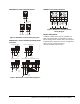
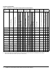

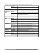
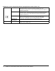
Table Of Contents

M9208-xxx-x Series Electric Spring Return Actuators Product Bulletin 5
M9208-Bxx-3 Series On/Off Actuators
M9208-AGx-x Series On/Off and Floating Point
Actuators
M9208-xxx-x Auxiliary Switches
Repair Information
A number of replacement parts are available; see
Table 3 for more details. If an M9208-xxx-x Series
Electric Spring Return Actuator fails to operate within
its specifications, replace the unit. For a replacement
electric actuator, contact the nearest
Johnson Controls® representative.
Figure 4: M9208-Bxx-3 Control Wiring Diagrams
AC 120 V 60 Hz
L1N
WHT BLK
2
1
AC 230 V 50/60 Hz
L1N
BLU BRN
2
1
AC 24 V 50/60
DC 24 V
RED
BLK
2
1
+
-
~
F
I
G
:
M
9
2
x
x
-
B
x
x
-
2
S
_
w
i
r
i
n
g
Figure 5: M9208-AGx-x Control Wiring Diagrams
~
+
-
24 VAC
24 VDC
RA
RA
DADA
4
BLK
RED
GRY
ORN
1
2
3
Floating Control, Four Wire
~
+
-
24 VAC
24 VDC
RA
RA
DADA
4
BLK
RED GRY ORN
1
2
3
On/Off Control, Two Wire
~
+
-
24 VAC
24 VDC
RA
RA
DADA
4
BLK
RED GRY ORN
1
2
3
Open/Close, Single Wire Control
FIG:M92xx-AGx_cntrlwir_PB
24 VAC
24 VDC
~
+
-
RA
RA
DADA
4
BLK
RED GRY ORN
1
2
3
RA
RA
DADA
4
BLK
RED GRY ORN
1
2
3
Floating Control, Multiple Actuators with One Transformer
Figure 6: M9208-xxx-x Auxiliary Switch
Wiring Diagram
COM
NC
NO
21
21
23
22
21
22
23
BLK/
RED
BLK/
BLU
BLK/
GRY
COM
NC
NO
24
25
26
WHT/
RED
WHT/
BLU
WHT/
GRY
25
24
24
26
S2
S1
FIG:xxC_Switch_Wiring