
Product Overview


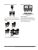
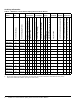

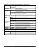
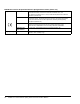
Table Of Contents

M9208-xxx-x Series Electric Spring Return Actuators Product Bulletin4
Wiring Diagrams
M9208-GGx-x Series Proportional Actuators
M9208-GGx-x Control Wiring Diagrams
Note: In master-slave applications, the slave actuator
lags the master actuator position by a few seconds.
IMPORTANT: Do not install multiple M9208-GGx-x
Series Actuators connected to the same mechanical
load. Master-slave application of M9208-GGx-x
Series Actuators requires that each actuator be
connected to independent loads.
Figure 2: M9208-GGx-x Control Wiring Diagrams
FIG:M9xxx-GGx_cntrlwi
r_PB
12
34
~
(+)
Y
COM
U
BLK
RED
GRY
ORN
0(4)...20 mA
+
+
500 / 0.25 W
ٛ
0(4)...20 mA Control with
External Resistor
AC/DC
24 V
DC 0(2)...10 V
1
2
34
~
(+)
Y
COM
U
BLK
RED
GRY
ORN
+
+
DC 0(2)...10 V Control
AC/DC
24 V
DC 0(2)...10 V
DC 0(2)...10 V
Master-Slave Application
Y
DC 0(2)...10 V
+
U
+
1
2
34
BLK
RED
GRY
ORN
AC/DC
24 v
~
(+)
DC 0(2)...10 V
COM
+
1
2
34
BLK
RED
GRY
ORN
Figure 3: M9208-GGx-x Control Wiring Diagram
(Overrides)
12
34
~
Y
COM
U
BLK
RED
GRY
ORN
+
+
Override to MIN position
AC
24 V
DC 0(2)...10 V
DC 0(2)...10 V
A
A Open = MIN Position
A Closed = Normal Operation
12
34
~
Y
COM
U
BLK
RED
GRY
ORN
+
+
Override to MAX position
AC
24 V
DC 0(2)...10 V
DC 0(2)...10 V
C
B Closed = MAX Position
C Closed = Normal Operation
B
1
2
3
4
~
COM
U
BLK
RED
GRY
ORN
+
+
Override to
MIN, MID, MAX positions
0(4)...20 mA Control with
External Resistor
AC
24 V
A
0(4)...20 mA
500 / 0.25 W
B
C
1
2
3
4
~
COM
U
BLK
RED GRY
ORN
+
+
Override to
MIN, MID, MAX positions
0(2)...10 V Control
AC
24 V
A
B
C
DC
0(2)...10 V
Y
FUNCTION
A
B
C
0% ( MIN )
50% ( MID )
100% ( MAX )
NORMAL
FUNCTION
A
B
C
0% ( MIN )
50% ( MID )
100% ( MAX )
NORMAL
Y
Ω
FIG:M9203GGx2(Z)_wir