
User's Manual

536636-UIM-D-1211
Johnson Controls Unitary Products 9
.
* Optional dehumidification humidistat switch contacts open on humidity rise.
NOTES:
1. “Y/Y2” Terminal on air handler control board must be connected for full CFM and applications requiring 60 second blower off delay for SEER enhancement.
2. Remove humidistat jumper on air handler control board.
3. For heat pump applications - set MODE jumper on air handler control board to the HP position.
4. To change quantity of heat during HP defrost cycle - reverse connections at W1 and W2 on air handler control board
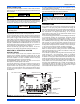
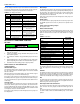
CONTROL WIRING USING COMMUNICATING
CONTROLS
Use the wiring diagram below to connect the air handler control, Com-
municating Control (wall thermostat) and communicating outdoor unit.
Be sure that all of the “A” terminals are connected together, all of the “B”
terminals are connected together, all of the “GND” or “C” terminals are
connected together and all of the “R” terminals are connected together.
See Figure 13. When using a fully communicating system, the large
screw terminals (C, G, R, etc.) on the air handler control are not used.
The four small screw terminals in the terminal block on the end of the air
handler control should be used.
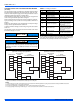
HUMIDITY SWITCH INPUT
The air handler control is designed to work with a humidity control that
closes when the humidity is below the set-point. The control is open
when the humidity is above the set-point. This humidity control may be
referred to as a humidistat or a dehumidistat.
The humidity switch controls both humidification and de-humidification
operation of the control. The control provides humidification using the
HUM OUT relay output and de-humidification by lowering the blower
speed. This is accomplished using the de-humidification input of the
motor for variable speed models. The humidity switch should be con-
nected to the R and HUM terminals of the control. See Figures 11 and
12.
The 24 volt power supply is provided by an internally wired low voltage
transformer which is standard on all models, However, if the unit is con-
nected to a 208 volt power supply, the low voltage transformer must be
rewired to the 208 volt tap. See the unit wiring label.
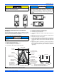
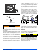
Field supplied low voltage wiring can exit the unit on the top right hand
corner or the right hand side panel. Refer to Figure 3.
Remove desired knockout and pierce foil faced insulation to allow wir-
ing to pass through. Use as small of a hole as possible to minimize air
leakage.
Install a 7/8” plastic bushing in the selected hole and keep low voltage
wiring as short as possible inside the control box.
To further minimize air leakage, seal the wiring entry point at the outside
of the unit.
The field wiring is to be connected at the screw terminals of the control
board. Refer to Figures 11 or 12.
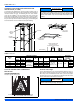
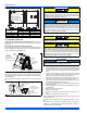
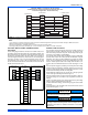
FIGURE 13: Two-Stage Heat Pump Wiring
CONTROL WIRING - Air Handler & UPG HP Systems
Two Stage H/P with York Guard VI Board & Copeland “Ultra Tech”
Conventional Application - Not Hot Heat Pump
THERMOSTAT
AIR HANDLER
BOARD
2 - STAGE SCROLL
HEAT PUMP
RR R
GG
Y2
E
W
W
O O
O
X / L X / L X / L
C
C
Y/Y2
Y1
Y1
Y2 OUT
Y2
W2 OUT
W1 OUT
BS
W2
W1
HUM
COM
HUMIDISTAT
*
Y1
FIGURE 14: Air Handler with Communicating AC or HP
A+
R
C
B-
A+
R
C
B-
A+
R
C
B-
R
G
Y/Y2
Y1
W2
W1
O
HUM
X/L
COM
Touch Screen
Communicating
Control
Air Handler
Communicating
Control
Air Conditioner/Heat Pump
Communicating Control
All wiring must comply with local and national electrical code require-
ments. Read and heed all unit caution labels.
It is possible to vary the amount of electric heat turned on during the
defrost cycle of a heat pump. Standard wiring will only bring on the
first stage of electric heat during defrost. See Heat Output and Limit
Connections and Table 5 for additional information on heat during
defrost cycle.
NOTICE
NOTICE