
User's Manual

536636-UIM-D-1211
Johnson Controls Unitary Products 11
The control energizes the first stage of electric heat immediately, the
second stage 10 seconds after the call for second stage heat, and the
third stage 20 seconds after the call for third stage heat.
Depending on the heat kit installed in the air handler, the control pro-
vides the flexibility to configure the amount of heat delivered with the
first stage heating call. As an example, when the control’s W1 input is
connected to the room thermostat’s first stage heat signal, a call for first
stage heat will energize one heating element (HT1). If the control’s W2
input is connected to the room thermostat’s first stage heat signal, a call
for first stage heat will energize two heating elements (HT1 and HT2).
With either configuration, the control will energize three heating ele-
ments (HT1, HT2, and HT3) when it receives a first and second stage
heat input from the thermostat.
Limit Switch and Lockout Operation
Limit Switch Operation
If the HEAT ENABLE jumper is in the HEAT position and the limit switch
opens (fault code 1), the control will immediately de-energize all electric
heat relay outputs and energize the blower (if it wasn’t already ener-
gized). When the limit switch closes, the control will re-energize electric
heat according to the thermostat inputs using normal timings.
Fan On Lock Condition
If the limit switch opens multiple times during a single call for electric
heat (fault code 3) or if the limit switch opens for a long duration (fault
code 4), the control will energize the blower until power is removed from
the control. The control will cycle the heat outputs on and off as the limit
re-closes and opens. The constant fan operation will signal the home-
owner that a problem has occurred and a service call is required.
Soft Lockout
If the limit switch opens for a second long duration period during a sin-
gle call for heat (fault code 5), the control will keep the blower locked on
and lock out the heat outputs for one hour. The control will only reset
this one hour lockout when the power is removed from the control. After
the one hour period has passed, the control will re-energize electric
heat according to the thermostat inputs using normal timings. The
blower will remain locked on from the first long duration limit opening.
Hard Lockout
The control has a hard lockout condition during which the control will
keep all heat outputs de-energized until power is removed from the con-
trol. The control de-energizes the blower five minutes after entering the
hard lockout condition.
If the limit switch closes and re-opens during the one hour soft lockout
period, the control will enter a hard lockout condition and continue to
indicate a fault code 5.
If the limit switch opens twice when no call for electric heat is present
(fault code 2), the control will enter a hard lockout condition.
If the limit switch opens multiple times soon after a soft lockout reset
(fault code 6), the control will enter a hard lockout condition.
Wiring Related Faults
If the control receives a simultaneous call for heating and cooling (fault
code 7), the control will perform both heating and cooling operations.
SECTION VII: LINE POWER
CONNECTIONS
Power may be brought into the unit through the supply air end of the
unit (top when unit is vertical) or the left side panel. Use the hole appro-
priate to the unit’s orientation in each installation to bring conduit from
the disconnect. The power lead conduit should be terminated at the
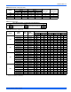
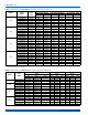
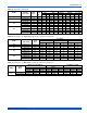
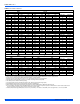
electrical control box. Refer to Tables 11, 12, 14 and 15 to determine
proper wire sizing. To minimize air leakage, seal the wiring entry point at
the outside of the unit.
All electrical connections to air handlers must be made with copper con-
ductors. Direct connection of aluminum wiring to air handlers is
not approved.
If aluminum conductors are present, all applicable local and national
codes must be followed when converting from aluminum to copper con-
ductors prior to connection to the air handler.
If wire other than uncoated (non-plated), 75° C ambient, copper wire is
used, consult applicable tables of the National Electic Code (ANSI/
NFPA 70). The chosen condutor and connections all must meet or
exceed the amperage rating of the overcurrent protector (circuit breaker
or fuse) in the circuit.
Additionally, existing aluminum wire within the structure must be sized
correctly for the application according to National Electric Code and
local codes. Caution must be used when sizing aluminum rather than
copper conductors, as aluminum conductors are rated for less current
than copper conductors of the same size.
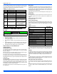
TABLE 5:
Heat Relays
Input Heat Relay Output
W1 HT1
W2 HT1 and HT2
W1 and W2 HT1 and HT2 and HT3
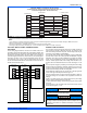
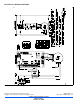
FIGURE 15: Line Power Connections
ELECTRIC HEAT
WITHOUT CIRCUIT BREAKER
SINGLE SOURCE (2.5 - 10 KW)
GND. LUG
POWER
SUPPLY
GND.
LUG
ELECTRIC HEAT
WITHOUT CIRCUIT BREAKER
3 PHASE (10 - 15 KW)
GND. LUG
POWER
SUPPLY
GND.
LUG
1 PHASE ELECTRIC HEAT
WITH CIRCUIT BREAKER
AS SHIPPED FROM FACTORY
SINGLE SOURCE
(2.5 - 25 KW) - 25 KW SHOWN
GND. LUG
POWER
SUPPLY
GND.
LUG
1 PHASE ELECTRIC HEAT
WITH CIRCUIT BREAKER
& BREAKER BAR REMOVED
MULTI-SOURCE (15 - 25 KW) - 25 KW SHOWN
GND. LUG
POWER
SUPPLY 1
GND.
LUG
POWER
SUPPLY 2
POWER
SUPPLY 3
TYPICAL WIRING WITHOUT ELECTRIC HEAT
GND. LUG
POWER
SUPPLY
GND.
LUG
POWER WIRING (208/230-1-60)
TERMINAL
BLOCK
TERMINAL
BLOCK
MAY BE 1, 2, OR 3
CIRCUIT BREAKERS
MAY BE 1, 2, OR 3
CIRCUIT BREAKERS
(JUMPER BAR)
CONNECT TRANSFORMER LEADS WITH
WIRE NUTS (TYPICAL ALL HEAT KITS)