
Install Instructions
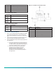
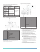
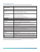
Table Of Contents

HL-6900 Multi-function Humidity Device with
Temperature Sensor Installation Guide
Installation
Important: The HL-6900 Series Multi-function
Humidity Device is intended to provide an input
to equipment under normal operating conditions.
Where failure or malfunction of the HL-6900 Device
could lead to personal injury or property damage
to the controlled equipment or other property,
additional precautions must be designed into the
control system. Incorporate and maintain other
devices, such as supervisory or alarm systems or
safety or limit controls, intended to warn of or
protect against failure or malfunction of the HL-6900
Device.
Important: Le HL-6900 Series Multi-function
Humidity Device est destiné à transmettre des
données entrantes à un équipement dans des
conditions normales de fonctionnement. Lorsqu'une
défaillance ou un dysfonctionnement du HL-6900
Device risque de provoquer des blessures ou
d'endommager l'équipement contrôlé ou un
autre équipement, la conception du système de
contrôle doit intégrer des dispositifs de protection
supplémentaires. Veiller dans ce cas à intégrer de
façon permanente d'autres dispositifs, tels que
des systèmes de supervision ou d'alarme, ou des
dispositifs de sécurité ou de limitation, ayant une
fonction d'avertissement ou de protection en cas
de défaillance ou de dysfonctionnement du HL-6900
Device.
Parts included
• HL-6900 Device
• Two 8 in. x 1 in. Phillips-head sheet metal screw
• Washer for use with conduit fitting; conduit fitting and
nut not provided
Tools required
• Hole saw with 1 in. (25 mm) diameter blade
• Drill with 1/8 in. (3 mm) drill bit
• No. 2 Phillips screwdriver
• Pliers
• Gasket, sealer, or other materials to seal the area
between the unit and the duct
Location requirements
Important: To avoid damage to the circuit board
and components, do not mount the unit in a location
where high concentrations of corrosive vapors are
present.
When you select a location for the HL-6900 Device,
consider the following:
• Position: The HL-6900 Device is designed for duct
mounting in any position, except with the probe tip
pointed up.
• Duct Diameter: Recommended minimum diameter
(round ducts) or width (square ducts) is 12 in. (305 mm).
• Air Stratification (when the unit is mounted on the
discharge side of the fan): Recommended location is
at least 8 ft (2.4 m) downstream from humidification
equipment, where duct air and water vapor are
sufficiently mixed. Avoid areas where the probe might
be exposed to condensation.
Application setup
Before installation, configure the multi-function humidity
device for the following: input and output signals, and
setpoint and proportional band.
The HL-6900 Device has a setpoint potentiometer,
adjustable from 60% to 95% Relative Humidity (RH), and
a proportional band potentiometer, adjustable from 5%
RH to 30% RH. See Figure 1 to change the setpoint or
proportional band for the application desired. See Table
1 and Table 2 for more details about the input and output
jumper setting.
Figure 1: Internal view of the HL-6900 Device
Callout Description
A Hole for mounting screw
B Input jumper
C Terminal block
D Proportional band potentiometer
E Output jumper
*241102500021-*
Part No. 24-11025-00021 Rev. —
2020-07-13
(barcode for factory use only)
HL-6900