
Install Instructions

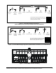
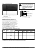
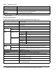
Table Of Contents

HE-6800 Series Humidity Transmitters with Temperature Sensor Installation Instructions 5
Humidity Output and Power Supply Selection
Switch
A 0 to 10 VDC or 0 to 5 VDC selector DIP switch
enables you to change the output for % RH. The
default factory setting is OFF (0 to 10 VDC output).
The HE-6800 also features a power supply selection
DIP switch. If you are using the transmitter where
supply voltage is 24 VAC or higher, set this switch to
ON.
Temperature Setpoint
Adjust the setpoint using the setpoint adjustment dial.
Rotate clockwise to raise the temperature; rotate
counterclockwise to lower the temperature.
Troubleshooting
HE-6800 Series Humidity Transmitters are
recommended for use only with Johnson Controls
digital controllers. If the HE-6800 is not functioning
properly, use the following procedure to identify the
problem and determine a solution:
1. Check that the HE-6800 is mounted in a location
indicative of the space temperature (for example,
away from drafts or sunlight).
2. Verify that the wiring is correct.
3. Check all supply voltage connections. See
Figure 1, Figure 2, or Figure 3, if necessary.
4. Check the settings:
• Verify that any scaling modifications, setpoint
adjustments, and overrides have been saved
and downloaded to the controller.
• Check the override status (Temporary
Occupancy mode vs. Unoccupied mode) at the
controller.
• Check the setpoint settings.
5. Confirm DIP switch positions if:
• the LED remains on or is dim
• the room sensor reading is outside of the
normal range for the space being sensed
Note: Make sure the DIP switch setting is correct for
the controller used with the HE-6800.
6. Replace the HE-6800 if the troubleshooting
suggestions fail to remedy the problem.
Accessories
Contact the nearest Johnson Controls representative
to order any of the parts listed in Table 4.
Note: Review the technical specifications of the
accessories prior to their use in an application.
Repair Information
Do not field repair the HE-6800 Series Humidity
Transmitters. As with any electrical device, keep the air
vents clean and free from dust or obstruction. If an
HE-6800 Series Humidity Transmitter fails to operate
within its specifications, replace the unit. For a
replacement transmitter, contact the nearest
Johnson Controls representative.
Table 3: LED Mode and Functions
LED Mode Functions Switch Positions
Enabled Disabled
OFF Sensor, PB LED Switch positions are down, up, and down. The LED remains off at all times.
ON LED, Sensor,
PB
--- Switch positions are factory set up, down, and up. The controller
determines the LED mode.
NO PB Sensor LED and PB Switch positions are all down. LED is off, and the PB does not function.
Figure 5: Humidity Output and Power Supply
DIP Switch Positions
DIP switch in the
default position.
KEY:
Switch is in up position (ON)
Switch is in down position (OFF)
NO
12
FIG:pwr_bst_ds
Switch 2
OFF = Low supply voltage operation
ON = High supply voltage operation
Switch 1
OFF = 0–10 VDC output, corresponding to 0–100%RH
ON = 0–5 VDC output, corresponding to 0–100%RH