
Install Instructions

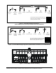
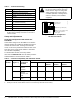
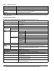
Table Of Contents

HE-6800 Series Humidity Transmitters with Temperature Sensor Installation Instructions 3
.
Figure 1: Terminal Block Wiring Designations
(LED ON Mode [Factory Default] and Manual Override PB Enabled)
RT
D
1
Temperature
Sensor
2
Temperature
Sensor
Common
3
Setpoint
Common
4
Setpoint
Setpoint
5
24 VAC/ +15 VDC
1k Ohms
6
Common
7
Zone Bus
Manual
Override
Button
8
LED
LED
Internal wiring diagram with DIP switches set as
shown on the right, LED Mode = ON and Manual
Override push button enabled.
FIG:term_blck_LED
NO
12
3
9
RH Output
0–10 VDC
Figure 2: Terminal Block Wiring Designations (LED OFF Mode and Manual Override PB Enabled)
RT
D
1
Temperature
Sensor
2
Temperature
Sensor
Common
3
Setpoint
Common
4
Setpoint
Setpoint
5
24 VAC/ +15 VDC
6
Common
7
Zone Bus
Manual
Override
Button
8
LED
LED
Internal wiring diagram with DIP switches set
as shown on the right, LED Mode = OFF and
Manual Override push button enabled.
FIG:term_blk_LED_OFF
Not Connected
NO
12
3
9
RH Output
0–10 VDC
Figure 3: Terminal Block Location and Wiring
FIG:term_blk