
Install Instructions
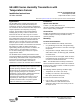

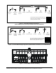
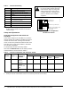
Table Of Contents

HE-6800 Series Humidity Transmitters with Temperature Sensor Installation Instructions2
2. Insert a blade screwdriver into the slot next to the
security screw location, and then carefully pry the
top edge of the transmitter assembly away from its
mounting base and remove.
3. Pull out approximately 6 in. (152 mm) of cable from
the wall, and insert the cable through the hole in
the mounting base.
4. Align the mounting base on the wall, and use the
base as a template to mark the location of the two
mounting holes on the surface.
Note: Make sure the mounting base is positioned
correctly with the security screw located on the top
edge of the base.
5. Secure the mounting base to the wall using the
appropriate mounting hardware (field furnished).
6. Set DIP switches for the desired operation. See the
Internal Wiring Diagrams
and Setup and
Adjustments sections for additional information.
7. Align the tabs on the bottom edge of the mounting
base with the slots on the bottom edge of the
transmitter assembly, and rotate the assembly onto
its mounting base.
Note: Make sure the terminal block pins align with the
holes in the terminal block.
8. Use a 1/16 in. (1.5 mm) Allen wrench or
Johnson Controls T-4000-119 Allen-Head
Adjustment Tool to tighten the security screw and
fasten the network transmitter assembly to the
mounting base.
Wiring
Keep wires as short as possible to minimize sensor
error. Each 250 ft (76 m) run of 18 AWG wire or
50 ft (15 m) of 24 AWG wire creates 1F° (0.56C°) error
for a nickel sensor or 1.5F° (0.83C°) error for a
platinum sensor due to wire resistance.
To maintain less than 1F° (0.56C°) error for nickel or
1.5F° (0.83C°) error for platinum, hold the total
resistance of all sensor wiring below 3 ohm. When
wiring the HE-6800, do not run low voltage wiring in the
same conduit as line voltage wiring or other conductors
supplying highly inductive loads.
Internal Wiring Diagrams
Internal wiring diagrams are shown in Figure 1 and
Figure 2. Terminal block designations are shown in
Figure 3. The terminals are identified in Table 1. See
the Setup and Adjustments
section and Figure 4 for an
explanation of the LED and Pushbutton (PB) modes.
Make connections pairing the following wires:
• sensor (Terminal 1 and Terminal 2)
• setpoint (Terminal 3 and Terminal 4)
• Zone Bus and Common (COM)
(Terminals 6 and 7)
Shielding is not required. If used, follow the system
controller’s recommendations for grounding the shield.
Note: The Manual Override PB does not respond
when the DIP switch positions are all down (LED mode
NO PB, as shown in Figure 2 and Figure 4).
Manual Override is selected for either Terminals 1 and
6 to short sensor (with DIP switch set for LED Off) or
Terminal 6 and Terminal 8 to short LED (with DIP
switch set for LED On).
IMPORTANT: Do not remove the Printed Circuit
Board (PCB). Removing the PCB voids the product
warranty.
!
CAUTION: Risk of Property Damage.
Do not apply power to the system before
checking all wiring connections. Short
circuited or improperly connected wires
may result in permanent damage to the
equipment.
IMPORTANT: Use copper conductors only. Make
all wiring connections in accordance with local,
national, and regional regulations.