
Install Instructions
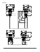
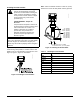
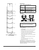
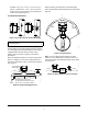
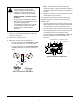

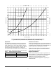
Table Of Contents

F261 Series Flow Switches Installation Instructions
5
Example: Use a 2 in. x 2 in. x 1 in. tee for a 2 in.
pipe. If a standard 2 in. x 2 in. x 2 in. tee is used,
install a face or hex bushing in the top opening to
reduce the top opening to 1 in.
Location Considerations
Mount the F261 flow switch in a horizontal pipeline or a
vertical pipeline with upward fluid flow. When mounted
in a vertical pipe with an upward flow, the switch trips at
a slightly higher flow than shown in Table 4 and
Table 5, due to the effect of gravity on the switch
mechanism.
Mount the F261 flow switch in a section of pipe where
there is a straight run of at least five pipe diameters
from the nearest elbow, valve, or other pipe restriction.
See Figure 8.
When mounting the flow switch on horizontal pipe,
mount the flow switch within 60 degrees of vertical. See
Figure 9.
Note: Do not subject the flow switches to water
hammer. Use a suitable water hammer arrester if a
fast-closing valve is located downstream of the switch.
See Figure 10.
IMPORTANT: Do not use in a vertical pipeline with
a downward flow.
Figure 7: Flow Direction for Vertical Mounting
FIG: Flw_dir
Figure 8: Required Piping Distance
FLOW FLOW
FLOW
Dimension must be at least
five pipe diameters from the nearest
elbow, valve, or other pipe restriction.
A
Tee or Welded
Half-Coupling
FIG:ppng_dst
nc
Figure 9: Angle Allowed
120° up
60°
from
vertical
60°
from
vertical
FIG:mtg_angl
Figure 10: Water Hammer Arrester Location
FLOW
FLOW
Water
Hammer
Arrester
FIG:wat_ham_arr