
Install Instructions
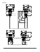
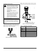
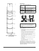
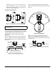
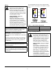
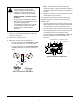

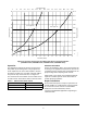
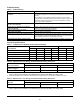
Table Of Contents

F261 Series Flow Switches Installation Instructions
4
Accessories
Mounting
Mount the F261 Series Flow Switches using the
following guidelines:
• Install the switch so that the enclosure and interior
are accessible.
• Mount the switch so that the flow of the fluid is in
the direction of the arrow on the enclosure.
• Use a pipe union on each side of the flow switch to
allow for easy removal or replacement.
• Do not allow the pipe to extend too far into the flow
switch casing.
• Use pipe thread sealer or teflon tape on the male
threads only.
• Do not remove the case-to-cover O-ring on
Type 4/IP67 enclosures.
For standard 1 in. x 1 in. pipe installation, mount the
F61 flow switch in a standard 1 in. x 1 in. x 1 in. tee. For
larger sizes of pipe, use a reducing tee to keep the flow
switch close to the pipe and provide adequate paddle
length in the flow stream.
Figure 5: Trimming Diagram for the
Large Flow Paddle
6 in. pipe
5 in. pipe
4 in. pipe
3 in. pipe
2-1/2 in. pipe
2 in. pipe
1-1/2 in. pipe
1 in. pipe
Original Length
FIG:pddl_tmplt
Table 2: Replacement Paddle Parts
Product
Code
Number
Description
KIT21A-600 Stainless steel 3-piece paddle
(3 in., 2 in., and 1 in. segments)
KIT21A-601 Stainless steel 6 in. paddle
PLT52A-600R Stainless steel 3-piece paddle
(3 in., 2 in., and 1 in. segments) and
Stainless steel 6 in. paddle
IMPORTANT: To avoid damaging the switch, do
not tighten the switch to the tee by grasping the
switch enclosure. Use only the wrench flats
provided.
Figure 6: Use Only the Wrench Flats Provided
FIG:wrnch_flts