
Install Instructions

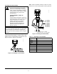
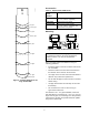
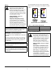
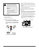
Table Of Contents

F261 Series Flow Switches Installation Instructions
7
To adjust the setting of the flow switch:
1. Disconnect the power supply before making any
electrical connections.
2. Remove the enclosure cover.
3. Adjust the control’s flow rate (Figure 12):
• Turn the adjustment screw clockwise to raise
the flow rate required to activate the switch.
• Turn the adjustment screw counterclockwise
to lower the flow rate required to activate the
switch.
Note: Do not lower the flow rate required to
activate the switch, unless the flow rate required to
activate the switch was raised from the factory-set
flow rate.
4. Replace the enclosure cover and tighten the cover
screws with 12 in•lb of torque.
To verify that the flow rate is set above the factory
minimum, depress the main lever (see Figure 13)
multiple times:
• if the lever clicks every time when returning to the
original position, then the control’s flow rate may be
set at or above the factory-set minimum value.
• if the lever fails to click every time when returning
to the original position, then the control’s flow rate
is set below the factory-set minimum value.
Turn the adjustment screw clockwise to raise the
flow rate required to activate the switch. See
Figure 12.
!
CAUTION: Risk of Property Damage.
Do not attempt to change sealed
settings. Attempted adjustment may
damage the control or cause loss of
calibration or other property damage.
MISE EN GARDE : Risque de dégâts
matériels.
Ne pas essayer de modifier la position
des éléments de réglage bloqués. Toute
tentative de réglage risque
d'endommager le dispositif de contrôle
ou de provoquer la perte des valeurs
d'étalonnage ou d'autres dégâts
matériels.
Figure 12: Flow Rate Adjustment
Red
Yell ow
Blue
+
-
Figure 13: Minimum Adjustment
main lever
adjustment screw
wiring terminals
FIG:F261_ctw
y_vw