
Install Instructions
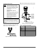
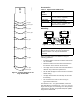
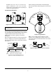

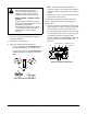
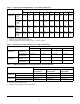
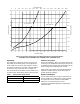
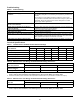
Table Of Contents

F261 Series Flow Switches Installation Instructions
9
Operation
The flow switch responds to pressure exerted on the
fluid paddle by the flowing fluid. A range adjustment
screw adjusts the rate of the flow required to activate
the switch. For flow rates, see Table 4 through Table 6.
For pressure drop versus flow rate, see Figure 14.
The red terminal is the Common. Red to Yellow closes
on flow increase. Red to Blue closes on flow decrease.
Checkout Procedure
Ensure that installation, wiring, and control settings are
according to the application requirements. Refer to the
controlled system’s manufacturer specifications for the
proper settings when adjusting these controls.
Apply power to the control and controlled equipment.
Cycle the controlled system at least three times at
normal operating conditions.
Repair Information
Do not make field repairs, except for replacement of
the flow paddle. For a replacement control or paddle
kit, contact the nearest Johnson Controls/PENN
distributor. For more information, contact
Johnson Controls/PENN application engineering at
1-800-275-5676.
Table 7: F261 Control Switch Action
Flow Action Switch Closure
Increase Red to Yellow
Decrease Red to Blue
Figure 14: Pressure Drop versus Flow Rate, F261 Series Low-Flow Switches
(F261KEH-V01C, F261MEH-V01C, F261KFH-V01C, F261MFH-V01C)
0 7.6 15.1 22.7 30.3 37.9
45.4 60.6 68.1 75.7 83.3 98.4
106
113.6
53.0
90.9
137.9
124.1
110.3
96.5
82.7
69.0
55.2
41.4
27.6
13.8
0
20
18
16
14
12
10
8
6
4
2
0
0 2 4 6 8 10121416182022242628
30
Flow Rate (L/Min)
P
ressure Drop (
P
SI)
Pressure Drop (kPa)
Flow Rate (GPM)
FIG:F261_LwFlw
1/2 in. pipe size
3/4 in. pipe size