
Install Instructions
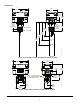
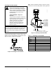
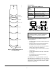
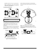

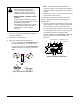
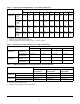
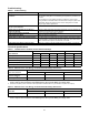
Table Of Contents

F261 Series Flow Switches Installation Instructions
3
Installing the Flow Paddles
Adjust the flow paddles to the size of the pipe used.
Install the large flow paddle, if needed. Trim the flow
paddle at the arc corresponding to the pipe size. See
Figure 3, Figure 4, Figure 5, and Table 1.
Note: Allow a minimum clearance of 3/16 in. (5 mm)
between the end of the flow paddle and the pipe wall.
!
WARNING: Risk of Personal Injury.
Shut off the liquid supply and relieve
pressure in the line before servicing the
valve. Contents of liquid lines could be
under pressure and the release of liquid
under pressure may cause severe
personal injury.
AVERTISSEMENT : Risque de
blessure.
Couper l'arrivée de liquide et évacuer la
pression présente dans la conduite avant
toute intervention sur la vanne. Les
liquides à l'intérieur des conduites
peuvent être sous pression et la
libération soudaine de liquide sous
pression risque de provoquer des
blessures graves.
IMPORTANT: The flow paddle must not touch the
pipe or any restrictions in the pipe. If the flow paddle
touches the pipe (or restrictions in the pipe), the
switch may not be able to properly detect changes in
fluid flow.
Figure 3: Installing the Flow Paddles
FIG:instl_flw_pddl
Table 1: Trimming the Flow Paddles
Paddle Size Use or Trim This Paddle to Fit
1 in. 1 in.
1-1/4 in. 2 in.
1-1/2 in. 2 in.
2 in. 2 in.
2-1/2 in. 3 in.
3 in. 3 in.
4 in. 6 in.
5 in. 6 in.
6 in. 6 in.
Figure 4: Trimming the Flow Paddles
1 in. [
1-1/4 in. [
1-1/2 in. [
2 in. [
2-1/2 in. [
3 in. [
4 in. [
5 in. [
6 in.
37 mm]
43 mm]
54 mm]
67 mm]
83 mm]
103 mm]
134 mm]
[162 mm]
29 mm]
b
b = 25 mm for the
b = 29 mm for the paddle 2, 3, or 6 in.
1 in. paddle
FIG:trm_flw_pddl