
Install Instructions
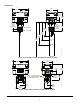
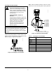
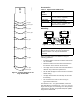
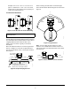

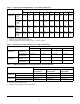
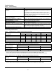
Table Of Contents

F261 Series Flow Switches Installation Instructions
10
Troubleshooting
Technical Specifications
Table 8: Troubleshooting
Symptom Solution
Water (condensate) appears within the
enclosure.
If the control has a Type 3R/IP43 enclosure, inspect the grommet in the
field-installed cable gland or conduit fitting, and replace the grommet if it is
defective.
If the control has a Type 4/IP67 enclosure, inspect the case-to-cover
O-ring provided on the flow switch. Ensure that the O-ring is in place and
undamaged. Ensure the control uses a correct cable gland or conduit
fitting for Type 4/IP67 applications.
Fluid from the tank leaks into the enclosure
due to a rod seal failure.
Replace the flow switch.
Switch does not activate due to debris in
switch mechanism.
Clear any debris from within the switch mechanism. Test the operation of
the switch several times for proper operation.
Control switch action is reversed. Ensure connections follow wiring diagrams.
Control does not switch. Check the electrical connections.
Switch fails to return to the no-flow position. The switch may be set lower than the factory setting. Increase the setting.
On vertical pipes, ensure that the direction of flow is up. The arrow on the
switch enclosure must point in the direction of the flow.
Control does not switch on flow increase. Check for a cracked or broken paddle. Replace the paddle, if necessary.
Table 9: F261xxH Series Standard Controls Electrical Ratings
Volts 50/60 Hz
UL60730/UL1059 EN60730
24 120 208 240 24 230
Horsepower –111––
Full Load Amperes –161010– 8
Locked Rotor Amperes –966060–48
Resistive Amperes 16 16 10 10 16 16
Pilot Duty VA 125 720 720 720 77 720
Table 10: F261xxL Series Low Energy Controls Electrical Ratings, AC Current
Volts AC, 50/60 Hz
UL60730/UL1059/EN60730
4 VAC 24 VAC 120 VAC
Resistive Amperes
1
10 10 10
Pilot Duty VA
2
12 72 360
1. Maximum Dry Circuit Rating: Resistive only, 400 mW at 28 VAC/VDC.
Once a relay has been used at the General Rating level, the Dry Circuit Rating is no longer valid.
2. Meets UL 100,000 cycle UL endurance test requirement at switch with T
min
greater than or equal to 32°F (0°C).
Table 11: F261xxL Series Low Energy Controls Electrical Ratings, DC Current
Volts DC
UL60730/UL1059/EN60730
4 VDC 24 VDC 48 VDC
Resistive Amperes
1
111
1. Maximum Dry Circuit Rating: Resistive only, 400 mW at 28 VAC/VDC.
Once a relay has been used at the General Rating level, the Dry Circuit Rating is no longer valid.