
Install Instructions
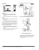
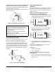
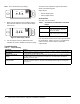
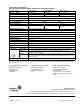
Table Of Contents

CSD Series Current Devices—Split Core Installation Instructions4
Note: This is the default factory setting.
2. Slowly turn the setpoint screw clockwise until the
Status Closed LED turns off and the Status Open
LED turns on.
3. Turn the setpoint screw an additional 1/4 turn
clockwise to create a deadband to prevent hunting.
The CSD is now calibrated to signal current flows
above normal load amperes.
Output Status:
• Normal: Output Open
• Alarm: Output Closed
Accessories
See Table 1 for accessories.
Repair Information
If the CSD Series Current Device fails to operate within
its specifications, replace the unit. For a replacement
CSD, contact the nearest Johnson Controls®
representative.
Troubleshooting
Figure 8: Status Closed, LED On
Status
Status
Open Setpoint
Closed
F
i
g
:
s
c
_
s
t
a
t
_
c
l
s
d
Figure 9: Status Open, LED On
Status
Status
Open Setpoint
Closed
F
i
g
:
s
c
_
s
t
a
t
_
o
p
n
Table 1: CR-01200-0 and CR-02400-0 Command
Relays
Product Code Product Description
CR-01200-0 12 VAC/VDC Single-Pole,
Single-Throw (SPST), Normally
Open (N.O.) Relay
CR-02400-0 24 VAC/VDC Single-Pole,
Single-Throw (SPST), N.O. Relay
Table 2: Troubleshooting
Symptom Action
CSD solid state output does
not function.
Verify the maximum amperage range has not been exceeded. Voltages or currents above
the rated levels may damage the CSD.
Setpoint screw keeps
turning.
The setpoint screw has a slip clutch to prevent damage at either end. To return the LED to
its original setting, turn the setpoint screw 20 full turns counterclockwise and start the
calibration procedure again.
Motor is turned on and switch
does not close.
Insufficient current to the load leads (for example, a motor or heater) to reach the setpoint
threshold. To turn the switch on, wrap the cable multiple times through the sensing hole
(see Figure 4).