
Install Instructions
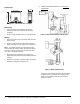
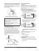
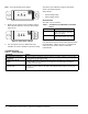
Table Of Contents

CSD Series Current Devices—Split Core Installation Instructions 3
If Measured Current Is Too Low to Be Detected
Wrap the conductor (wire) through the sensing hole
and around the CSD body to produce multiple turns to
increase the measured current.
Measured current = actual current times the number of
turns (see Figure 4).
To Monitor Currents Exceeding the Maximum
Current Rating of the CSD
For currents > 135 A (Model CSD-CA1G0-1), > 200 A
(Model CSD-CF0A0-1 or Model CSD-CF0J0-1).
Use a 5 A Current Transformer (CT) to reduce the
current passing through the CSD as shown in Figure 5.
Run the current transformer secondary wire through
the sensing hole. Terminate the two secondary wires of
the 5 A current transformer to each other, and then
install the 5 A current transformer on the monitored
conductor.
Setup and Adjustments
Calibration
Position the CSD so the status output panel faces you.
Confirm the monitored load (for example, a motor or
heater) is running, and use the following methods to
calibrate the CSD.
Under Current Status Condition (Belt Loss,
Coupling Shear, Fan, and Pump Status)
1. Turn the setpoint screw clockwise until the Status
Closed Light-Emitting Diode (LED) turns off and
the Status Open LED turns on.
2. Slowly turn the setpoint screw counterclockwise
until the Status Closed LED turns on and the
Status Open LED turns off.
3. Turn the setpoint screw an additional 1/4 turn
counterclockwise to create a deadband to prevent
hunting.
The CSD is now calibrated to signal current flows
below normal full load amperes.
Output Status:
• Normal: Output Closed
• Alarm: Output Open
Over Current Status Condition (Locked Rotor,
Seized Impeller)
1. Turn the setpoint screw counterclockwise until the
Status Open LED turns off and the Status Closed
LED turns on.
IMPORTANT: Failure to derate the current capacity
could result in damage to the CSD when using
multiple turns to increase measured current. Use the
the following formula to determine the new
maximum current:
New Maximum Current = CSD Current Rating/
number of turns. For example,
Model CSD-CA1G0-1 with 4 turns = 135 A/4 = 33.8,
new maximum current.
Figure 4: CSD Shown with Four Turns
F
i
g
:
s
c
_
t
r
n
s
Figure 5: CSD with CT Transformer
Current > 135 A
F
i
g
:
s
p
c
_
w
c
t
Figure 6: Status Open, LED On
Status
Status
Open Setpoint
Closed
F
i
g
:
s
c
_
s
t
a
t
_
o
p
n
Figure 7: Status Open, LED Off
Status
Status
Open Setpoint
Closed
F
i
g
:
s
c
_
s
t
a
t
_
c
l
s
d