
Install Instructions
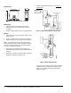
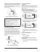
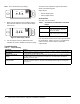
Table Of Contents

CSD Series Current Devices—Split Core Installation Instructions2
Dimensions
Mounting
1. Using the two screws (included), attach the
mounting bracket to the back of the electrical
enclosure.
2. Snap the CSD into place on the mounting bracket.
Wiring
1. Disconnect power to the conductor cable from the
power source.
2. Snap the split core around the power conductor
cable, and close the core until the core snaps shut.
Note: The switch contacts are solid state and they
work just like dry contacts. When the switch is closed,
less than 1 ohm is present; when the switch is open,
more than 1 megohm is present.
3. Wire CSD output terminals to the control box
Digital Input (DI) terminal (30 V maximum terminal
voltage).
4. Reconnect the power conductor cable. (For wiring
example, see Figure 2 and Figure 3.)
5. Calibrate Model CSD-CA1G0-1 (see Setup and
Adjustments).
If the measured current is too low to be detected or
is higher than the maximum current rating of the
CSD, use the following methods to increase or
decrease current.
Figure 1: CSD Dimensions, mm (in.)
27 (1-1/16)
Fig:sc_sde
65 (2-9/16)
69 (2-23/32)
Fig:splt_cre_frnt
Figure 2: Model CSD-CF0A0-1/CSD-CF0J0-1
Power
Source
Building Automation
Controller
Heating Element
Fan or Pump
DI
DI
Power
Source
F
I
g
:
s
c
_
w
r
e
Figure 3: Model CSD-CA1G0-1
Contactor
DI
Motor
Fan or Pump