
User Guide
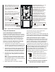
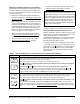
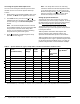
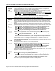
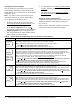
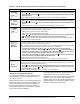
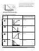
Table Of Contents

System 450™ Series Control Modules with Relay Outputs Installation Instructions 9
Setting up an Analog Output (OUTA
x
)
An analog output provides an analog signal to control
your application based on a fixed setpoint sensor
(Sn-1, Sn-2, or Sn-3).
Analog outputs provide an auto-selecting analog signal
that is proportional to the sensed input condition. The
System 450 analog output senses the impedance of
the controlled equipment’s analog input circuit and
automatically delivers either a 0–10 VDC or 4–20 mA
signal to the controlled equipment.
The control action between the input signal and the
output signal can be set up four different ways,
depending on the values selected for the Setpoint (SP),
End Point (EP), Percent Output Signal Strength at
Setpoint (OSP), and Percent Output Signal Strength at
End Point (OEP). The LCD displays different Control
Ramp icons for the four control actions.
Minimum Relay ON Time Selection Screen: Minimum ON Time range is 0 to 300 seconds.
5. Press or to select the minimum time that the output relay remains On after reaching the
Relay ON value, then press
to save your selection and go to the Minimum Relay OFF Time
Selection Screen.
Screen example shows 0 (zero) seconds selected for the minimum ON-Time for Output 1.
Minimum Relay OFF Time Selection Screen: Minimum OFF Time range is 0 to 300 seconds.
6. Press or to select the minimum time that this output relay remains Off after reaching the
Relay OFF value. Press
to save your selection and go to the Sensor Failure Mode Selection
screen.
Screen example shows 120 seconds selected for the minimum OFF-Time for Output 1.
Sensor Failure Mode Selection Screen: Select this output’s mode of operation if the referenced sensor
or sensor wiring fails. The output operates in the selected mode until the failure is remedied.
Sensor Failure mode selections for Relay Outputs include:
• ON output relay remains On during sensor failure.
• OFF output relay remains Off during sensor failure.
7. Press or to select this output mode of operation if the sensor or sensor wiring fails. Press
to save your sensor failure mode selection and go to the Edit Sensor Screen.
Screen example shows OFF sensor failure mode selected for Output 1. This output relay is Off if the
referenced sensor or sensor wiring fails.
Edit Sensor Screen: This screen displays the sensor that this output currently references. Typically, no
action is taken in this screen. But if you need to change the sensor that this output references, you
can select a different sensor for this output in this screen.
Note: Changing the sensor that an output references to a sensor with a different Sensor Type changes
the default setup values for the output, and requires setting up the output again.
8. To change this output’s sensor, Press or to select the sensor that this output will
reference. After you select a different sensor for this output, press
to return to the Relay ON
Selection screen (Step 3 above) and repeat the output relay setup procedure for this output
and the new Sensor Type values associated with the new sensor selection.
If you do not need to change this output’s sensor, simply press
to save the current sensor
selection and return to the Relay Output Setup Start screen.
This Relay Output is now set up in the System 450 UI.
Screen example shows input Sensor 2 selected for Output 1 (Output 1 references Sensor 2).
Relay Output Setup Start Screen
After you have set up this Relay Output, you can go to another Output Setup Start screen, the Sensor
Setup Start screen, or return to the Main screens.
9. Press to scroll through the remaining Output Setup Start screens and return to the Sensor
Setup Start screen, or press and simultaneously and hold for 5 seconds to return to the
System 450 Main screens.
Screen example shows the Relay Output Setup-Start screen for Output 1.
Table 5: System 450 Relay Output Setup Screen Information and Procedures (Continued)
LCD Screen Name, Description/Function, User Action, and Example
ONT
1
0
OFFT
1
120
SNF
1
OFF
Sn-2
SENS
OUTR
1
-- -
M