
User Guide
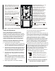
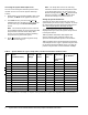
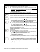
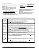
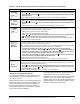
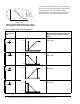
Table Of Contents

System 450™ Series Control Modules with Relay Outputs Installation Instructions6
Accessing the System 450 Setup Screens
You can access the System 450 setup screens from
the Main screen. To access the System 450 setup
screens:
1. Apply power to your module assembly. After a start
up check, the Main screen appears on the LCD.
2. In the Main screen, press and hold
and
simultaneously for 5 seconds to access the setup
screens and to go to the Sensor Setup Start
screen.
Note: The Sensor Setup Start screen is the first
screen displayed when you access the System 450
setup screens. From the Sensor Setup Start
screen, you can navigate to all of the remaining
setup screens for your control system.
3. Press
repeatedly to scroll through the Setup
Start screens. See Figure 7.
Note: The Setup Start screens are view-only;
selections cannot be made in Setup Start screens.
In any Setup Start screen, you can return to the
Main screens by pressing and simultaneously.
Also, the UI returns to the Main screens after 2
minutes of inactivity in any screen in the UI.
Setting up System 450 Sensors
You must set up the input sensors for your control
system before you can set up any of outputs. To set up
the input sensors you must access the setup screens.
See Accessing the System 450 Setup Screens
.
The Sensor Setup Start screen is the first screen
displayed when you access the system setup screens
in the System 450 UI.
Table 3 provides information about System 450
sensors, Sensor Types, parameter values, and
specified sensor/transducer product code numbers.
Table 4 provides sensor setup information, procedures,
and example screens. Figure 7 provides a System 450
UI and setup overview example. Figure 7 on page 14
provides a System 450 UI screen flowchart example.
.
M
Table 3: System 450 Sensor Types, Setup Values, and Sensor/Transducer Product Codes
Sensor
Type
Unit of Measurement
Value
(Condition/Units)
Effective
Sensing
Range
Range of
Usable
Values
Resolution
Increment
Value
Minimum
Differential
or
Proportional
Band
Sensor Product
Type Number
1
°F °F (Temperature/degrees) -46 to 255 -40 to 250 1 1 A99B-xxx
°C °C (Temperature/degrees) -43 to 124 -40 to 121 0.5 0.5 A99B-xxx
rH % (Humidity/%RH) 1 to 100 10 to 95 1 2 HE-67Sx-xxxxx
P 05 INWC (Pressure/in. W.C.) 0 to 0.5 0.025 to 0.5 0.005 0.025 DPT2650-0R5D-AB
P 8 bAR (Pressure/bar) -1 to 8 -1 to 8 0.05 0.1 P499Rxx-401C
P 10 INWC (Pressure/in. W.C.) 0 to 10 0.5 to 10 0.05 0.2 DPT2650-10D-AB
P 15 bAR (Pressure/bar) -1 to 15 -1 to 15 0.1 0.2 P499Rxx-402C
P 30 bAR (Pressure/bar) 0 to 30 0 to 30 0.1 0.4 P499Rxx-404C
P 50 bAR (Pressure/bar) 0 to 50 0 to 50 0.2 0.4 P499Rxx-405C
P100 PSI (Pressure/psi) 0 to 100 0 to 100 0.5 1 P499Rxx-101C
P200 PSI (Pressure/psi) 0 to 200 0 to 200 1 1 P499Rxx-102C
P500 PSI (Pressure/psi) 0 to 500 90 to 500 1 5 P499Rxx-105C
P750 PSI (Pressure/psi) 0 to 750 150 to 750 2 6 P499Rxx-107C
1. Refer to the System 450 Series Modular Controls Product Bulletin (LIT-12011458), Catalog Page (LIT-1900549), or
Technical Bulletin (LIT-12011459) for complete ordering information for System 450 compatible sensors and transducers.