
User Guide
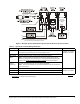
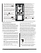
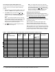
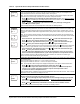
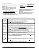
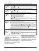
Table Of Contents

System 450™ Series Control Modules with Relay Outputs Installation Instructions 3
Table 1: System 450 Terminal Wiring Information
Label Terminal Function Wire Sizes
24V Accepts 24 VAC supply power, when a C450YNN power module is not connected,
and provides power terminal for 24 VAC (humidity) sensors.
0.08 mm
2
to 1.5 mm
2
28 AWG to 16 AWG
5V Provides 5 VDC power for active sensors.
Sn-1, Sn-2,
Sn-3
Accepts passive or active (0-5 VDC) input signals from sensors.
Note: You must position the Active/Passive Sensor Jumper (Figure 3 and
Figure 6) correctly for each sensor in your control system before operating the
system. See Setting Active/Passive Sensor Jumpers
for more information.
C
(Three
Terminals)
Provide low-voltage Common connections for 24 VAC power and passive or active
sensors connected to the 5V, Sn1, Sn2, and Sn3 terminals.
Note: The three C terminals are connected internally and can be connected to
ground in the field.
LNC1, LNC2 Connects control circuit to the Normally Close (NC) contact on the SPDT relay.
0.08 mm
2
to 2.5 mm
2
28 AWG to 14 AWG
LNO1, LNO2 Connects control circuit to the Normally Open (NO) contact on the SPDT relay.
LC1, LC2
Connects line (power) to Common (C) on the SPDT
1
relay.
1. See Internal SPDT Relay insert in Figure 2 for more System 450 relay contact and terminal information. See Technical
Specifications for SPDT relay electrical ratings.
Figure 3: Example System 450 Heat/Cool System with Condenser Fan Speed Control
FIG:sys450_app_exmpl
L2
L1
L2
L1
0-10 VDC or
4-20 mA
Analog Output
Signal
L1 L2
AO2
COM
AO1
Note:
In 120 VAC applications, L1 must be the Hot lead
and L2 must be the Neutral/Common lead.
Sn-1
Sn-2
Sn-3
Active/Passive Sensor Jumpers