
User Guide
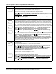
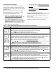
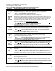
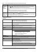
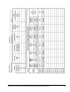

Table Of Contents

System 450™ Series Control Modules with Relay Outputs Installation Instructions12
Technical Specifications
Sensor Failure Mode Selection Screen:
8. Press or to select this output’s mode of operation if the sensor or sensor wiring fails.
Press
to save your selection and go to the Edit Sensor Selection screen.
You can select this output’s mode of operation in the event of a sensor or sensor wiring failure. The output
operates in the selected mode until the failure is fixed. Sensor Failure Mode selections for Analog Outputs
include:
• ON - output generates maximum signal strength during sensor failure.
• OFF- output generates minimum signal strength during sensor failure.
Screen example shows the OFF Sensor Failure Mode selected for Output 3.
Edit Sensor Selection Screen: Press or to change the sensor that this output references (only if
required), then press
to go to this output’s setup start screen.
Note: Changing the sensor that an output references to a sensor with a different Sensor Type changes
the default setup values for the output, and requires setting up the output again.
Screen example shows input Sensor 1 selected for Output 3.
Table 7: System 450 Analog Output Setup Screens Information (Part 2 of 2)
LCD Screen Name, Description/Function, User Action, Example
SNF
3
OFF
SENS
3
Sn-1
C450CxN-1
Product C450CxN-1: System 450 Control Modules are sensing controls and operating controls
with LCD, four-button touch pad, and On/Off relay output.
C450CBN-1: Control Module with one SPDT output relay
C450CCN-1: Control Module with two SPDT output relays
Supply Power C450YNN-1 Power Supply Module or
24 (20-30) VAC Safety Extra-Low Voltage (SELV) (Europe) Class 2 (North America)
50/60 Hz, 10 VA minimum
Ambient Operating Conditions Temperature: -40 to 66°C (-40 to 150°F)
Humidity: Up to 95% RH noncondensing; Maximum Dew Point 29°C (85°F)
Ambient Shipping and Storage
Conditions
Temperature: -40 to 80°C (-40 to 176°F)
Humidity: Up to 95% RH noncondensing; Maximum Dew Point 29°C (85°F)
Input Signal 0-5 VDC; 1035 ohms at 25°C (77°F) for an A99 PTC Temperature Sensor
Output Relay Contacts General: 1/2 HP at 120/240 VAC, SPDT
Specific: AC Motor Ratings 120 VAC 208/240 VAC
AC Full-load Amperes: 9.8 A 4.9 A
AC Locked-Rotor Amperes: 58.8 A 29.4 A
_____________________________________
10 Amperes AC Non-inductive at 24/240 VAC
Pilot Duty: 125 VA at 24/240 VAC
Analog Input Resolution: 14 bit
Control Construction Independently-mounted control, surface mounted with Lexan® 950 enclosure suitable
for DIN rail mounting or direct mounting to a hard, even surface.
Dimensions (H x W x D) 127 x 61 x 61 mm (5 x 2-3/8 x 2-3/8 in.)
Weight C450CBN-1: 209 gm (0.46 lb)
C450CCN-1: 222 gm (0.49 lb)
Compliance North America: cULus Listed; UL 60730, File E27734, Vol. 1; FCC Compliant to
CFR47, Part 15, Subpart B, Class B
Industry Canada (IC) Compliant to Canadian ICES-003, Class B limits
Europe: Mark: CE Compliant; Low Voltage Directive (2006/95/EC); EMC Directive
(2004/108/EC); RoHS Directive (2002/95/EC); WEEE Directive (2002/96/EC)
Australia: Mark: C-Tick Compliant (N1813)