
User Guide
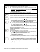
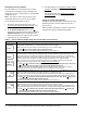
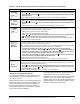
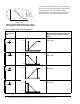
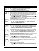
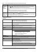
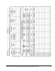

Table Of Contents

System 450™ Series Control Modules with Relay Outputs Installation Instructions 11
See Table 7 for setup information, procedures, and
screen examples for analog outputs.
Table 7: System 450 Analog Output Setup Screens Information (Part 1 of 2)
LCD Screen Name, Description/Function, User Action, Example
Analog Output Setup Start Screen: The output number and output type (relay or analog) are
automatically assigned when you connect power to your control system’s module assembly.
Note: You must set up the system’s sensors before you can set up the outputs.
1. Press
to go to this output’s Sensor Selection screen.
Screen example shows the Analog Output Setup-Start screen for Output 3.
Sensor Selection Screen: The sensor you select here determines this output’s setup parameters and
values, including condition type, unit of measurement, minimum proportional band, default setup values,
and setup value ranges for several of the remaining output setup screens. If a sensor is not selected here,
this output’s remaining setup screens do not appear. If a sensor is already selected for this output, the
Sensor Selection screen does not appear here, instead the Setpoint Selection screen appears.
Note: You must select a sensor in this Sensor Selection screen and the selected sensor must be already
set up in the System 450 UI. (See Setting up System 450 Sensors
.)
2. Press or to select the Sensor (Sn-1, Sn-2, or Sn-3) that this output references. Press
to
save your sensor selection and go to the Setpoint Selection screen.
Screen example shows input Sensor 1 (Sn-1) selected for Output 3.
Setpoint Selection Screen: Setpoint is the target value that the controlled system drives towards and
along with End Point, defines this output’s proportional band.
Note: An output’s minimum proportional band (between Setpoint and End Point) is automatically
enforced in the output’s Setpoint and End Point Selection screens.
3. Press or to select this output’s Setpoint value. Press
to save your Setpoint value
selection and go to the End Point Selection screen.
Screen example shows a Setpoint of 200 (psi) selected for Output 3.
End Point Selection Screen: End Point is the (condition) value that the controlled system drives away
from (towards Setpoint) and, along with Setpoint, defines this output’s proportional band.
Note: An output’s proportional band (between Setpoint and End Point) is automatically enforced in the
output’s Setpoint and End Point Selection screens.
4. Press or to select this output’s End Point value. Press
to save your End Point value
selection and go to the %Output Signal Strength at Setpoint Selection screen.
Screen example shows a End Point of 250 (psi) selected for Output 3.
Output Signal Strength at Setpoint Selection Screen: Select the strength of the signal that this output
generates when the sensed condition is at the Setpoint value. The signal strength range is 0 to 100 (%).
5. Press or to select this output’s %Output Signal Strength at Setpoint value. Press
to
save your selection and go to the %Output Signal Strength at End Point Selection screen.
Screen example shows Analog Output 3 is setup to generate 10% of the total signal strength when the
input is at the Setpoint value (= 1 V or 5.6 mA).
Output Signal Strength at End Point Selection Screen: Select the strength of the signal that this output
generates when the sensed condition is at the End Point value. The signal strength range is
0 to 100 (%).
6. Press or to select this output’s %Output Signal Strength at End Point value. Press
to
save your selection and go to the Integration Constant Selection screen.
Screen example shows Output 3 is set up to generate 90% of the total signal strength when the input is at
the End Point value (= 9 V or 18.4 mA).
Integration Constant Selection Screen: An integration constant allows you to set up proportional plus
integral control for this analog output. proportional plus integral control can drive the load closer to
Setpoint than proportional only control.
Note: Initially, you should select the I-C value of 0 (zero) for no integration constant. Refer to the System
450 Series Technical Bulletin (LIT-12011459) for more information on proportional plus integral control
and setting an integration constant in the System 450 UI.
7. Press or to select this output’s Integration Constant for proportional plus integral control.
Press
to save your selection and go to the Sensor Failure Mode Selection screen.
Screen example shows an Integration Constant of 0 (zero) selected for Output 3.
OUTA
3
-- -
SENS
3
Sn-1
SP
3
200
EP
3
250
OSP
3
10
OEP
3
90
I-C
3
0