
User Guide
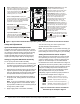
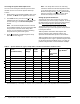
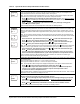
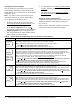
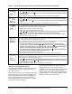
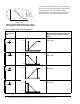
Table Of Contents

System 450™ Series Control Modules with Relay Outputs Installation Instructions10
Figure 6 shows an example of the analog output setup
values and the resulting output signal in a typical space
heating application (SP > EP and OSP < OEP).
Table 6 shows the four Control Ramp icons and the
associated analog output setup value relationships.
S
y
s
t
e
m
O
u
t
p
u
t
0%
100%
Condition Value
Less Greater
65
°F
10%
70
°F
SP > EP
SP = 70 ( )
EP = 65 ( )
OSP = 10 (%)
OEP = 100 (%)
°F
°F
OSP < OEP
OSP
OEP
S
P
E
P
Proportional
Band
Fig:sys450_cntrl_rmp_exmpl
Figure 6: Control Ramp Example for a Typical
Heating Application (SP > EP and OSP < OEP)
Table 6: Analog Output Control Ramp Icons
Control Ramp
Displayed on
LCD
Control Action Set the Analog Output Value
Relationships for the Desired Control
Action and Corresponding Control
Ramp
SP < EP
OSP < OEP
SP > EP
OSP < OEP
SP > EP
OSP > OEP
SP < EP
OSP > OEP
Output Minimum at SP
P
r
o
p
o
r
t
i
o
n
a
l
B
a
n
d
OEP=100%
OSP=0%
SP=50°F EP=60°
F
Output Minimum at SP
P
r
o
p
o
r
t
i
o
n
a
l
B
a
n
d
EP=50°F SP=60°F
OEP=100%
OSP=0%
Output Maximum at SP
OSP=100%
OEP=0%
EP=50°F SP=60°F
P
r
o
p
o
r
t
i
o
n
a
l
B
a
n
d
Output Maximum at SP
SP=50°F EP=60°F
OSP=100%
OEP=0%
P
r
o
p
o
r
t
i
o
n
a
l
B
a
n
d