
Install Instructions
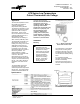
Table Of Contents

Installation Sheets Manual 121
Temperature Controls Section
Technical Bulletin A70
Issue Date 0492
© 1992 Johnson Controls, Inc. 1
Code No. LIT-121116
Part No. 997-742
A70 Series Low Temperature
Cutout Thermostat Line Voltage
Application
The A70 low temperature cutout
thermostats have electrical
contacts operated by a
temperature sensing element.
The switching mechanism on the
single-pole, single-throw models
opens the circuit on a drop in
temperature. On the 4-wire,
two-circuit models the main load
contacts (LINE-M2) open on a
temperature drop and
simultaneously the auxiliary or
alarm contacts (LINE-M1) close.
The thermostat is used as a low
temperature cutout device on
heating and cooling coils or other
applications where there is a
possibility of air being stratified.
It responds only to the lowest
temperature along the 20 feet of
the sensing element. The
sensing element is usually
located on the downstream side
of the coil. When the
temperature at any point along
the sensing element reaches the
set point, the thermostat will stop
the fan. The outdoor damper is
installed to close when the fan
stops.
The thermostats with manual
reset will lock out when the
sensed temperature drops below
the set point. The reset must be
pushed and released before the
contacts can be reclosed.
All Series A70 thermostats are
designed for use
only
as
operating controls. Where an
operating control failure
would result in personal injury
and/or loss of property, it is
the responsibility of the
installer to add devices
(safety, limit controls) that
protect against, or systems
(alarm, supervisory systems)
that warn of, control failure.
Installation
Mounting
!
CAUTION: Locate the
thermostat case and
bellows where the ambient
temperature is always
warmer than the set point.
The thermostat operates
only from the lowest
temperature along the
entire 20 foot sensing
element. Avoid sharp
bends or kinks in the
sensing elements.
The thermostat may be mounted
to a wall surface or panel board
using the two mounting holes
provided in the back of the case.
The desired mounting position is
with the element bellows pointing
down.
For accurate thermostat
operation, the sensing element
should be horizontally
serpentined across the face of
the coil to sense temperature in
all areas.
Fig. 1 -- Electric thermostat
shown with manual reset.
Specifications