
Install Instructions
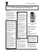
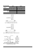
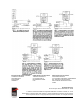
Table Of Contents

2 A19BAC, A28AA Installation Instructions
wall. Avoid locations near a door,
window or hay chute.
IMPORTANT: Do not dent or
deform the sensitive bulb of
this thermostat. A dent or
deformation will change the
calibration and cause the
thermostat to cycle at a
temperature lower than the
dial setting.
Adjustment
Knob adjustment or screwdriver slot
is supplied on the range screw. Dial
pointer is located on adjustment
stop bracket on knob and
screwdriver adjustment models.
Before removing the cover, verify
that all power to the thermostat and
associated equipment is turned off.
!
WARNING: Risk of
Electric Shock.
Disconnect or isolate all power
supplies before making
electrical connections. More
than one disconnection or
isolation may be required to
completely de-energize
equipment. Contact with
components carrying
hazardous voltage can cause
electric shock and may result in
severe personal injury or death.
AVERTISSEMENT : Risque
de décharge électrique.
Débrancher ou isoler toute
alimentation avant de réaliser
un branchement électrique.
Plusieurs isolations et
débranchements sont peut-être
nécessaires pour -couper
entièrement l'alimentation de
l'équipement. Tout contact
avec des composants
conducteurs de tensions
dangereuses risque d'entraîner
une décharge électrique et de
provoquer des blessures
graves, voire mortelles.
Solid cover models are adjusted by
removing cover and moving dial so
that the setpoint is in line with the
dial pointer on the stop bracket.
(See Fig. 3.)
Convertible adjustment models can
be field converted from concealed
screwdriver slot adjustment to knob
adjustment or external screwdriver
slot adjustment. They are supplied
with a snap-in plug in the cover to
provide concealed screwdriver slot
adjustment. For knob adjustment
remove the snap-in plug and press
the knob onto the slotted shaft. For
external screwdriver slot adjustment
remove the snap-in plug.
The A28AA switch is stamped to
indicate the HI-TEMP switch and
the LO-TEMP switch.
Fig. 2 -- The Space Thermostats
with convertible adjustment have
a snap-in plug in the cover, built-
in screwdriver slot and a knob
for field installation.
A high temperature adjustment stop
is supplied on the thermostats. (See
Fig. 3.) If adjustment stop is
required:
1. Set dial to temperature at
which stop is desired.
2. Remove cover from thermostat.
3. Loosen the adjustment stop
screw, slide the screw to the
front of the thermostat against
the plastic stop cam behind the
dial and tighten the screw. (See
Fig. 3.)
Sometimes an exact stop
setting is not possible and stop
must be set to the closest step
corresponding to dial setting
required.
4. Turn dial to setpoint desired.
5. Replace cover.
Wiring
!
WARNING: Risk of Electric
Shock.
Disconnect or isolate all power
supplies before making electrical
connections. More than one
disconnection or isolation may be
required to completely de-energize
equipment. Contact with
components carrying hazardous
voltage can cause electric shock
and may result in severe personal
injury or death.
ADVERTISSEMENT : Risque de
décharge électrique.
Débrancher ou isoler toute
alimentation avant de réaliser un
branchement électrique. Plusieurs
isolations et débranchements sont
peut-être nécessaires pour -couper
entièrement l'alimentation de
l'équipement. Tout contact avec des
composants conducteurs de
tensions dangereuses risque
d'entraîner une décharge électrique
et de provoquer des blessures
graves, voire mortelles.
All wiring should conform to local,
national, and regional codes. Use
copper conductors only. Do not use
on applications where electrical
ratings exceed ratings shown on the
thermostat’s cover label.
See Figs. 4 through 11 for typical
wiring applications.
Note: Use terminal screws
furnished (8-32 × 1/4 in. binder
head). Substitution of other screws
may cause problems in making
proper connections.
Checkout Procedure
Before leaving the installation,
observe at least three complete
operating cycles to be sure that all
components are functioning
correctly.