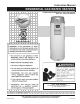
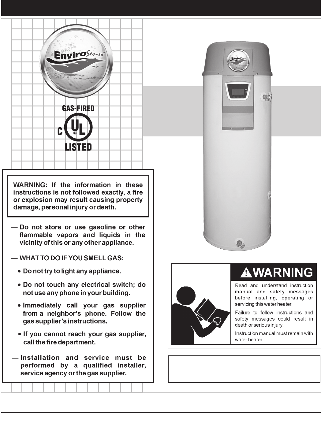
Instruction Manual RESIDENTIAL GAS WATER HEATERS POWER VENT/POWER DIRECT VENT GAS MODELS WITH HOT SURFACE IGNITION CANADIAN MANUAL • For Your Safety • AN ODORANT IS ADDED TO THE GAS USED BY THIS WATER HEATER. ALL TECHNICAL AND WARRANTY QUESTIONS: SHOULD BE DIRECTED TO THE LOCAL DEALER FROM WHOM THE WATER HEATER WAS PURCHASED. IF YOU ARE UNSUCCESSFUL, CALL THE TECHNICAL SUPPORT PHONE NUMBER SHOWN ON THE WATER HEATER LABELING.
SAFE INSTALLATION, USE AND SERVICE Your safety and the safety of others is extremely important in the installation, use and servicing of this water heater. Many safety-related messages and instructions have been provided in this manual and on your own water heater to warn you and others of a potential injury hazard. Read and obey all safety messages and instructions throughout this manual.
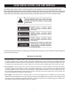
GENERAL SAFETY 3
GENERAL SAFETY 4
TABLE OF CONTENTS SAFE INSTALLATION, USE AND SERVICE............................2 GENERAL SAFETY..................................................................3 TABLE OF CONTENTS.............................................................5 INTRODUCTION.......................................................................5 Preparing for the Installation..............................................5 Get to Know Your Water Heater.........................................6 INSTALLATION CONSIDERATIONS......
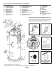
GET TO KNOW YOUR WATER HEATER - GAS MODELS A Control Assembly B Blocked Inlet Switch C Blocked Outlet Switch D Fan Prover Switch E Blower Assembly F Burner Assembly G Flame Sensor H Hot Surface Igniter I Junction Box J Gas Valve Assembly K Display Board L Top Plastic Enclosure M Display Enclosure ** N Exhaust Elbow Assembly ** O Condensate Tubing P Off/On Switch Q Display Label R Hot Water Outlet *S Electrical Outlet (120VAC) T Gas Supply U Main Manual Gas
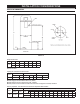
INSTALLATION CONSIDERATIONS ROUGH IN DIMENSIONS FIGURE 1A. Rough-In-Dimensions Model 100 Units A B C D E Inches cm F 68.50 49.25 22.00 15.75 3.00 8.00 174 125.09 55.88 40.00 7.62 20.32 Top/Side Inlet and Outlet: 3/4” NPT Gas Inlet: 1/2” NPT Capacity, Gas and Electrical Characteristics Model 100 Approximate Capacity Manifold Pressure Electrical Characteristics U.S. Gals. Liters Gas Type “WC kPA Volts/Hz Amperes 50 189 Nat.
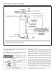
WATER PIPING - MIXING VALVE USAGE * The side recirculation loop connections may not be used as the primary water inlet and outlet connections. For your convenience, plugs are installed in these fittings at the factory. Remove these plugs if needed for your specific installation. Otherwise (as with all connections) check for leaks while filling the tank with water and after completing the installation. FIGURE 2.
Facts to Consider About the Location Carefully choose an indoor location for the new water heater, because the placement is a very important consideration for the safety of the occupants in the building and for the most economical use of the appliance. This water heater is not for use in manufactured (mobile) homes or outdoor installation. Whether replacing an old water heater or putting the water heater in a new location, the following critical points must be observed: 1.
in an alcove or closet, the entire floor must be covered by the panel. Failure to heed this warning may result in a fire hazard. for placement on the blanket directly over the existing labels. • Do inspect the insulation blanket frequently to make certain it does not sag, thereby obstructing combustion air flow. COMBUSTION AIR AND VENTILATION A gas water heater cannot operate properly without the correct amount of air for combustion.
a free area of one square inch per 1000 Btu/hr (22 cm2/kW) of the total input of all appliances in the enclosure, but not less than 100 square inches (645 cm2). Btu per hour (11 cm2/kW)) of total input rating of all equipment in the enclosure, see Figure 9. If the confined space is within a building of tight construction, air for combustion and ventilation must be obtained from outdoors.
INSTALLING THE NEW WATER HEATER CHEMICAL VAPOR CORROSION CLOSED WATER SYSTEMS CORROSION OF THE FLUEWAYS AND VENT SYSTEM MAY OCCUR IF AIR FOR COMBUSTION CONTAINS CERTAIN CHEMICAL VAPORS. SUCH CORROSION MAY RESULT IN FAILURE AND RISK OF ASPHYXIATION. Water supply systems may, because of code requirements or such conditions as high line pressure, among others, have installed devices such as pressure reducing valves, check valves, and back flow preventers.
Figures 2 and 10 show the typical attachment of the water piping to the water heater. The water heater is equipped with 3/4 inch NPT water connections. If replaced, the valve must meet the requirements of local codes, but not less than a combination temperature and pressure relief valve certified as indicated in the above paragraph. NOTE: If using copper tubing, solder tubing to an adapter before attaching the adapter to the water heater connections.
HIGH ALTITUDE INSTALLATIONS The temperature-pressure relief valve must be manually operated periodically, see Figure 28. Caution should be taken to ensure that (1) no one is in front of or around the outlet of the temperature-pressure relief valve discharge line, and (2) the water manually discharged will not cause any bodily injury or property damage because the water may be extremely hot.
VENTING SEDIMENT TRAPS A sediment trap shall be installed as close to the gas inlet of the water heater as practical at the time of water heater installation. The sediment trap shall be either a tee fitting with a capped nipple in the bottom outlet or other device recognized as an effective sediment trap. Contaminants in the gas lines may cause improper operation of the gas control valve that may result in fire or explosion. Before attaching the gas line be sure that all gas pipe is clean on the inside.
CAUTION TO PREVENT EXHAUSTING PRODUCTS FROM CIRCULATING TO THE AIR INTAKE IN WINDY/COLD AREAS, THE MAXIMUM PRACTICAL DISTANCE BETWEEN THESE TWO TERMINALS IS RECOMMENDED. CANADIAN POWER VENT WARNING VENT HOOD(S) MAY BE EXTREMELY HOT DURING OPERATION. FIGURE 12.
CAUTION TO PREVENT EXHAUSTING PRODUCTS FROM CIRCULATING TO THE AIR INTAKE IN WINDY/COLD AREAS, THE MAXIMUM PRACTICAL DISTANCE BETWEEN THESE TWO TERMINALS IS RECOMMENDED. CANADIAN DIRECT VENT WARNING VENT HOOD(S) MAY BE EXTREMELY HOT DURING OPERATION. FIGURE 13.
PLANNING THE VENT SYSTEM joints between elbows and other fittings and straight runs of vent pipe. Check system for signs of sagging or other stresses in joints as a result of misalignment of any components in the system. If any of these conditions are found, they must be corrected in accordance with the venting instructions in this manual before completing installation and putting the water heater into service.
INSTALLATION OF VENT SYSTEM DIRECT VENTING Before beginning installation of piping system thoroughly read the section of this manual VENT PIPE PREPARATION. The air intake provided on the unit contains a mesh screen to prevent large particles from entering the unit. If you are installing your system so that it vents through roof, please refer to section titled INSTALLATION OF VERTICAL VENT SYSTEM. VENT TERMINAL INSTALLATION, SIDEWALL 1.
INSTALLATION SEQUENCE VERTICAL VENT TERMINAL INSTALLATION CAUTION IMPORTANT VENT TERMINALS SUPPLIED WITH HEATER MUST BE USED. WHEN TERMINATING THROUGH A ROOF, THE FOLLOWING SPECIFICATIONS PERTAINING TO TERMINAL LOCATION MUST BE FOLLOWED. NOTE: BEFORE BEGINNING INSTALLATION OF ANY VENT PIPE READ THE VENT PIPE MANUFACTURER’S INSTALLATION INSTRUCTIONS. 1. Proper support must be provided for all pipe protruding through the roof. 1.
INSTALLATION OF VENT SYSTEM, SIDEWALL With the route of the venting system and selection of materials completed, as discussed in the section of this manual titled PLANNING THE VENT SYSTEM, the through the wall vent terminal in place and the first section of piping, up to first elbow, installed at the blower it is time to complete the installation of the venting system for the sidewall installation. FIGURE 23.
This concentric vent termination kit may be used with 3 or 4 inch diameter pipe systems. When connecting to a 4 in. diameter pipe system a 3 x 4 inch field supplied reducer is to be installed at the intake and exhaust connection of the concentric vent termination kit. 1. Determine best location for termination kit. NOTE: Roof termination is preferred since it is less susceptible to damage, has reduced chances to intake contaminants, and less visible vent vapors. 2. Cut 1 hole (5 in.
NOTE: See the venting information (pages 16-20) in this 5. Secure assembly to roof structure as shown in Figure E using field supplied metal strapping or equivalent support material. NOTE: Ensure termination height is above the roof surface or anticipated snow level as shown in Figure C. manual for additional vent location requirements. 2. Cut 1 hole (5 in. diameter) 3. P a r t i a l l y a s s e m b l e c o n c e n t r i c v e n t t e r m i n a t i o n k i t . 6.
8. Operate heater through 1 heat cycle to ensure combustion-air and vent pipes are properly connected to concentric vent termination connections. Figure 31. Concentric Vent Terminations for Horizontal Direct Venting. Figure 30. MULTI-CONCENTRIC VENT TERMINATIONS When two or more appliances are directed vented with concentric vent terminations near each other, each appliance must be individually vented. NEVER common vent this appliance.
VENT PIPE PREPARATION PRIMER 1. INITIAL PREPARATION. It is recommended that Tetrahydrofuran (THF) be used to prepare the surfaces of pipe and fittings for solvent welding. Do not use water, rags, gasoline or any other substitutes for cleaning PVC or CPVC surfaces. A chemical cleaner such as MEK may be used. A.) Make sure the solvent cement you are planning to use is designed for the specific application you are attempting. B.
B. Deburring Use a knife, plastic pipe deburring tool, or file to remove burrs from the end of small diameter pipe. Be sure to remove all burrs from around the inside as well as the outside of the pipe. A slight chamfer (bevel) of about 10°-15° should be added to the end to permit easier insertion of the pipe into the end of the fitting. Failure to chamfer the edge of the pipe may remove cement from the fitting socket, causing the joint to leak. STEP B C.
CONTROLS AND SWITCHES open. When this switch prevents the unit from igniting, most likely the exhaust is blocked by some means. Check to see if the condensate is allowed to flow freely from the exhaust elbow and for obstructions in the exhaust venting and exhaust vent terminal. Also verify that the vent length does not exceed the maximum allowed as shown in the Vent Section of this manual. This model is provided with three pressure switches.
CAUTION LABEL ALL WIRES PRIOR TO DISCONNECTION WHEN SERVICING CONTROLS. WIRING ERRORS CAN CAUSE IMPROPER AND DANGEROUS OPERATION. VERIFY PROPER OPERATION AFTER SERVICING. THIS WATER HEATER IS POLARITY SENSITVE. B EFO R E A PPLYI N G ELECTRICITY TO THIS HEATER BE CERTAIN THAT SUPPLY NEUTRAL WIRE TO GROUND CHECK INDICATES ZERO VOLTAGE. POWER VENT WIRING SCHEMATIC - FIGURE 34.
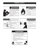
FOR YOUR SAFETY READ BEFORE LIGHTING WARNING: If you do not follow these instructions exactly, a fire or explosion may result causing property damage, personal injury or loss of life. BEFORE OPERATING: ENTIRE SYSTEM MUST BE FILLED WITH WATER AND AIR PURGED FROM ALL LINES. A. This appliance does not have a pilot. It is equipped with an ignition device which automatically lights the burner. Do NOT try to light the burner by hand. B. BEFORE OPERATING smell all around the appliance area for gas.
TEMPERATURE REGULATION It is recommended that lower water temperatures be used to avoid the risk of scalding. It is further recommended, in all cases, that the water temperatures be set for the lowest temperature which satisfies your hot water needs. This will also provide the most energy efficient operation of the water heater. The water temperature is controlled using the Temperature Control on the Display at the front of the unit (See Figure 1).
USING THE ELECTRONIC CONTROLLER 1. Overview Interaction with the water heater controller is done through an up, a down, and three operation buttons. These buttons are illustrated to the right. Operation of the three lower buttons is defined immediately above them on the screen. The [UP] and [DN] buttons are used to navigate through the menus and make adjustments to the water heater.
2. Operating States In the main desktop screen, there are some specific Operating States that are indicated on the status line. These are summarized below: 3. Adjusting the Operating Set Point ACTION: From the Main Menu, press Select to enter the "Temperatures" screen. The Operating Set Point of this water heater determines the regulated temperature for the water in the tank. This parameter is adjusted in the Temperature menu.
3. Changing the Display Units There are two types of conditions that can occur during operation. These are Alerts and Faults: The display interface to the heater has the option of selecting between degrees Fahrenheit and degrees Celsius for temperature displays. This can be found in the “Display Settings” menu. Also in this menu, you may adjust how the backlight operates and the contrast of the LCD screen.
6. Viewing the Fault History ACTION: To get to the current fault information screen, press Menu. The controller for this water heater will store a history of ten of the last Fault and Alert conditions that occurred. This is stored in the Fault History. Along with all the information about the fault, including a estimate time of when the fault occurred, information regarding the advanced diagnostics for that fault can be accessed at any time. DISPLAY: ACTION: Press the DOWN button for more information.
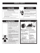
FOR YOUR INFORMATION START UP CONDITIONS OPERATIONAL CONDITIONS SMOKE/ODOR It is not uncommon to experience a small amount of smoke and odor during the initial start-up. This is due to burning off of oil from metal parts, and will disappear in a short while. SMELLY WATER In each water heater there is installed at least one anode rod (see parts section) for corrosion protection of the tank. Certain water conditions will cause a reaction between this rod and the water.
PERIODIC MAINTENANCE Venting System Inspection Soot build-up indicates a problem that requires correction before further use. Turn “OFF” gas to water heater and leave off until repairs are made, because failure to correct the cause of the sooting can result in a fire causing death, serious injury, or property damage. Burner Cleaning In the event your burner or burner air openings require cleaning, turn the on/off switch to the “OFF” position and allow the unit to cool.
Certain water conditions will cause a reaction between the anode rod and the water. The most common complaint associated with the anode rod is a “rotten egg smell” produced from the presence of hydrogen sulfide gas dissolved in the water. IMPORTANT: Do not remove this rod permanently as it will void any warranties. The parts list includes a special anode rod that can be ordered if water odor or discoloration occurs. NOTE: This rod may reduce but not eliminate water odor problems.
Service the water heater contact a qualified service agency. If you are not thoroughly familiar with gas codes, your water heater, and safety practices, contact your gas supplier or qualified installer to check the water heater. Use this guide to check a “Leaking” water heater. Many suspected “Leakers” are not leaking tanks. Often the source of the water can be found and corrected. Read this manual first.
TROUBLESHOOTING GUIDELINES These guidelines should be utilized by a qualified service agent. PROBLEMS 1.) Blower will not run. a. “ON/OFF” control switch turned off. Turn switch to the “ON” position. b. Blower unplugged. Plug blower back into 115 VAC outlet. c. No power at outlet. Repair service to outlet. d. Thermostat defective. Replace thermostat. e. Control harness defective. Replace control harness. f. High limit control circuit open. Reduce the water temperature below 140°F.
NOTES 40
Limited Warranty THIS WARRANTY IS APPLICABLE TO THE ORIGINAL OWNER ONLY.
GSW Water Heating 599 Hill Street West Fergus, ON Canada N1M 2X1 Should you have any questions please Email us at techsupport@gsw-wh.com or Visit our websites: www.gsw-wh.com or www.johnwoodwaterheaters.com or Call our Technical Support line at 1-888-GSW-TECH (479-8324) GSW Water Heating is a division of A.O.Smith Enterprises Ltd.