O P E R A T O R ’ S M A N U A L FERTILIZER SPREADERS SS1023B SS1036B SS1067B SS2036B SS2067B Manual 5BP960376B Date 05/19/2011
SAFETY Take note! This safety alert symbol found throughout this manual is used to call your attention to instructions involving your personal safety and the safety of others. Failure to follow these instructions can result in injury or death. This symbol means: ATTENTION! BECOME ALERT! YOUR SAFETY IS INVOLVED! Signal Words Note the use of the signal words DANGER, WARNING and CAUTION with the safety messages.
INDEX 1 - GENERAL INFORMATION 4 1.01 - General 4 1.02 - Model and Serial Number ID 4 1.03 - Assembly Instructions for Model SS1023B 5 1.04 - Assembly Instructions for Models SS1036B & SS2036B 6 1.05 - Assembly Instructions for Models SS1067B & SS2067B 8 2 - SAFETY PRECAUTIONS 11 2.01 - Preparation 11 2.02 - Starting and Stopping 11 2.03 - Messages and Signs 12 3 - OPERATION 14 3.01 - Operational Safety 14 3.02 - Set Up 15 3.03 - Pre-Operational Check 15 3.
FERTILIZER SPREADERS OPERATOR’S MANUAL 1 - GENERAL INFORMATION Thank you and congratulations for having chosen our implement. Your new fertilizer spreader is a technologically advanced machine constructed of high quality sturdy components that will fulfill your working expectations. Read this manual carefully. It will instruct you on how to operate and service your fertilizer spreader safely and correctly. Failure to do so could result in personal injury and/or equipment damage. 1.
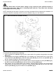
FERTILIZER SPREADERS OPERATOR’S MANUAL 1.03 - Assembly Instructions for Model SS1023B CAUTION: Stand clear of bands when cutting as they could be under sufficient tension to cause them to fly loose. Take care in removing bands and wire. They often have extremely sharp edges and cut very easily. NOTE: Assembly will be easier if all parts are loosely assembled before tightening the hardware. All hardware needed for assembly will be found in the hardware bag or on the machine.
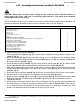
FERTILIZER SPREADERS OPERATOR’S MANUAL Fig. 2 - Model SS1023 assembly. 1.04 - Assembly Instructions for Models SS1036B & SS2036B Each unit is shipped with a hardware bag that consists of the following: Description Spreader disc (#21, fig. 3) Shutter assembly Protection (#5, fig. 3) Lever (#16, fig. 3) Scaled rod assembly (#18, fig. 3) Stationary stirrer (#20, fig. 3) Protection (#4, fig. 3) Driveline Hardware bag contains the following: Attachment plate (5BP0014338) (#6, fig.
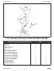
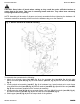
FERTILIZER SPREADERS OPERATOR’S MANUAL CAUTION: Stand clear of bands when cutting as they could be under sufficient tension to cause them to fly loose. Take care in removing bands and wire. They often have extremely sharp edges and cut very easily. NOTE: Assembly will be easier if all parts are loosely assembled before tightening the hardware. All hardware needed for assembly will be found in the hardware bag or on the machine. Fig. 3 - Model SS1036B & SS2036B assembly.
FERTILIZER SPREADERS OPERATOR’S MANUAL 5. Install the stationary stirrer (see #20, fig. 3) using M8x45 hex bolt (see #31, fig. 3), two Ø8 flat washers (see #38, fig. 3), and one M8 elastic stop nut (see #36, fig. 3) that are already bolted to the stirrer. 6. Install protection (see #5, fig. 3) using two M8x20 carriage bolts (see #28, fig. 3), two Ø10 fender washers (see #42, fig. 3), two Ø8 lock washers (see #40, fig. 3) and secure with two M8 hex nuts (see #34, fig. 3).
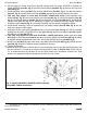
FERTILIZER SPREADERS OPERATOR’S MANUAL CAUTION: Stand clear of bands when cutting as they could be under sufficient tension to cause them to fly loose. Take care in removing bands and wire. They often have extremely sharp edges and cut very easily. NOTE: Assembly will be easier if all parts are loosely assembled before tightening the hardware. All hardware needed for assembly will be found in the hardware bag or on the machine. Fig. 4 - Models SS1067B & SS2067B assembly.
FERTILIZER SPREADERS OPERATOR’S MANUAL 5. Secure hopper to frame using three M12x30 carriage bolts on model SS1067B or M12x40 on model SS2067B (see #23, fig. 4), three Ø14 flat washers (see #24, fig. 4), and six M12 hex nuts (see #25 fig. 4). 6. Install stationary stirrer (see #21, fig. 4) using M8x45 bolt (see #39, fig. 4), two Ø8 flat washers (see #27, fig. 4), and M8 elastic stop nut (see #40, fig. 4) that are already bolted to the stirrer. 7.
FERTILIZER SPREADERS OPERATOR’S MANUAL 2 - SAFETY PRECAUTIONS Safety is the primary concern in the design and manufacture of our products. Unfortunately our efforts to provide safe equipment can be wiped out by a single careless act of an operator. In addition to the design and configuration of equipment, hazard control and accident prevention are dependent upon the awareness, concern, prudence and proper training of personnel involved in the operation, transport, maintenance and storage of equipment.
FERTILIZER SPREADERS OPERATOR’S MANUAL 3. The operating power is supplied from tractor PTO. Refer to your tractor manual for PTO engagement and disengagement instructions. Always operate PTO at 540 rpm. Know how to stop the tractor and machine quickly in case of an emergency. 4. When engaging PTO, the engine rpm should always be low. Once engaged and ready to start operating, raise PTO speed to 540 rpm and maintain throughout operation. 5. Check the tractor master shield over the PTO stub shaft.
FERTILIZER SPREADERS OPERATOR’S MANUAL Safety decals - implement; replace immediately if damaged.
FERTILIZER SPREADERS OPERATOR’S MANUAL 3 - OPERATION The fertilizer spreader is versatile and ideal for granular or powdered fertilizers, seed and sand. It may also be used as a salt spreader for snow or ice covered roads during winter months. Our spreaders are designed for tractors from 16 to 30 PTO HP with a category 1 three point hitch. Spreaders can be used for broadcast spreading or may be used to spread prevalently to the left or to the right with a simple adjustment.
FERTILIZER SPREADERS OPERATOR’S MANUAL 16. Stay alert for holes, rocks and roots in the terrain and other hidden hazards. Keep away from drop-offs. 17. Use extreme care and maintain minimum ground speed when transporting on hillside, over rough ground and when operating close to ditches or fences. Be careful when turning sharp corners. 18. Reduce speed on slopes and sharp turns to minimize tipping or loss of control. Be careful when changing directions on slopes. Do not start or stop suddenly on slopes.
FERTILIZER SPREADERS OPERATOR’S MANUAL 3.04 - Attaching to the Tractor Unit may be used on tractors ranging from 16 to 30 HP equipped with a standard rear PTO and category 1 three point hitch6. Never use this spreader with tractors over 30 HP. DANGER: Do not allow anyone to stand between spreader and tractor while attaching implement. WARNING: Never attempt to attach the implement to the tractor or make an adjustment to it without first turning the tractor off.
FERTILIZER SPREADERS OPERATOR’S MANUAL operation. If it was necessary to remove the PTO shielding to do any of the above operations, do not forget to replace it. 3.05 - Start Up CAUTION: Load hopper with product only after the spreader has been properly attached to the tractor. WARNING: Chemicals may cause eye, skin or breathing problems. Always wear a face mask, gloves and goggles when filling hopper. Refer to chemical manufacturer’s label for specific safety information.
FERTILIZER SPREADERS OPERATOR’S MANUAL WARNING: Before engaging the PTO, be sure no persons or animals are behind or beside the spreader. DANGER: Never allow anyone within 50 yards of the spreader while the PTO is engaged. Product thrown from the spreader can cause serious injury or death. DANGER: Never allow any person inside the hopper for any reason. Serious injury or death can result from someone becoming entangled in the agitator.
FERTILIZER SPREADERS OPERATOR’S MANUAL Fig. 8 Three different ways of spreading. Spread adjustment for Models SS1036B, SS2036B, SS1067B & SS2067B: These fertilizer spreaders have two ways of regulating material distribution: 1. Adjusting the spread position. 2. Adjusting the quantity of material being spread. Adjusting the spread position: The machine can be adjusted to spread to the center or off to either of the two sides. This is accomplished by opening the left gate (see #15, fig.
FERTILIZER SPREADERS OPERATOR’S MANUAL Use Table 48 to determine the approximate amount of material to be spread in lbs./acre at a 46 foot spreading width and put the lever into that position on the sliding scale. Example: With the lever in position 5, a ground speed of 5 mph, spreading at 46 ft., the output should be approximately 246 lbs. per acre. Fig. 9 Moving the wings in a clockwise position will obtain more of a left spread pattern.
FERTILIZER SPREADERS OPERATOR’S MANUAL 4 - MAINTENANCE DANGER: Stop engine, lock parking brake and remove key before performing any service or maintenance. Always use personal protection devices, such as a breathing mask capable of filtering toxic powders, safety glasses and gloves, when performing maintenance. Refer to chemical manufacturer’s label for specific safety information. Keep fingers out of slots to prevent injury. 4.01 - Maintenance Safety 1. Good maintenance is your responsibility. 2.
FERTILIZER SPREADERS OPERATOR’S MANUAL 16. Unauthorized modifications to the machine may impair the function and/or safety of the machine and reduce its life. If equipment has been altered in any way from original design, the manufacturer does not accept any liability for injury or warranty. 4.02 - Service Before beginning work: 1. Apply a thick layer of grease to all exposed moving parts. 2.
FERTILIZER SPREADERS OPERATOR’S MANUAL If determined that the driveline is too long, follow these procedures to adjust the length: 1. Separate the two driveline halves. Connect one half to the tractor PTO and the other half to the implement. 2. Raise and lower the implement with the 3 point hitch to find the position where the driveline is shortest.
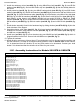
FERTILIZER SPREADERS OPERATOR’S MANUAL TABLE 1 - TORQUE SPECIFICATIONS Metric (ISO) treaded bolts head marking Inch (SAE) treaded bolts head marking Class 5.8 Bolt size mm Thread mm N.m ft-lb Class 8.8 N.m ft-lb Grade 2 Class 10.9 Grade 8 ft-lb Thread inch tpi N.m ft-lb N.m ft-lb N.
FERTILIZER SPREADERS OPERATOR’S MANUAL TABLE 3 - MODEL SS1023B SWATH SPREAD PATTERNS (lbs/acre) Lever position 2.5 mph Spreading width 20 feet 3.75 mph 5 mph 1 89 45 39 2 143 89 71 3 223 152 107 4 312 196 152 5 419 277 205 6 553 330 277 7 651 410 321 8 767 473 384 9 874 562 437 10 999 625 500 TABLE 4 - MODELS SS1036B, SS2036B, SS1067B & SS2067B SWATH SPREAD PATTERNS (lbs/acre) Lever position 2.5 mph MAINTENANCE Spreading width 46 feet 5 mph 7.
FERTILIZER SPREADERS OPERATOR’S MANUAL 5 - REPAIR PROCEDURES CAUTION: All repair procedures must be done by authorized dealerships. It is not recommended that untrained individuals perform any repair work. 5.
FERTILIZER SPREADERS OPERATOR’S MANUAL 6 - TROUBLESHOOTING WARNING: Be sure tractor engine is off, parking brake is locked, and key is removed before making any adjustments. PROBLEM POSSIBLE CAUSE Non uniform spread Spreader disc wings not positioned properly. pattern. Product not flowing to spreader disc. PTO shaft turning but not the gearbox output shaft. Narrow spread width. TROUBLESHOOTING SOLUTION Position spreader disc wings to the proper setting (see section 3.06 - Operating Techniques).
FERTILIZER SPREADERS OPERATOR’S MANUAL 7 - PRE-DELIVERY CHECKLIST To the dealer: Inspect the machine thoroughly after assembly to assure it is functioning properly before delivering it to the customer. The following checklist is a reminder of points to cover. Check off each item as it is found satisfactory or after proper adjustment is made. Gearbox oil level. Guards and shield properly fastened. Lubrication of grease fittings. All hardware properly tightened.
P A R T S M A N U A L FERTILIZER SPREADERS SS1023B SS1036B SS1067B SS2036B SS2067B Note: Serial #’s with the XF prefix are subsequent to serial numbers with the BC prefix. For example: A reference to “serial # BC… 739197 & above” will also include all serial numbers with an XF prefix. Frontier Hop 203, 206, 209 (US) Printed on May 19, 2011 Parts Manual 05/2011 203-120 Ver. D 206-121, 206-221 Ver. B 209-121, 209-421, 209-422 Ver.
FERTILIZER SPREADERS PARTS MANUAL 02/2011 FRAME SS1023B 32 OPERATOR’S MANUAL FRONTIER
FERTILIZER SPREADERS Ref. 1 2 3 4 5 6 7 8 9 10 11 15 17 18 19 20 21 22 23 24 25 26 27 28 29 30 31 11 OPERATOR’S MANUAL Part # 5BP501660B 5BP0014620 5BP0014616 5BP501661B 5BP501668B 5BP501630B 5BP501631B 5BP501639B 5BP501123B 5BP501622B 5BP501652B 5BP501650B 5BP501670B 5BP0014710 5BP501663B 5BP0015230 5BP0014514 5BP0001806 5BP0046454 5BP0011209 5BP0015220 5BP0091384 5BP501651B 5BP0041291 5BP0015273 5BP0002034 5BP0001280 5BP0090150 Description Frame w/cat. 0/1 hitch; SS1023B #XF...
FERTILIZER SPREADERS PARTS MANUAL 05/2011 FRAME SS1036B 34 OPERATOR’S MANUAL FRONTIER
FERTILIZER SPREADERS Ref.
FERTILIZER SPREADERS PARTS MANUAL 05/2011 FRAME SS2036B 36 OPERATOR’S MANUAL FRONTIER
FERTILIZER SPREADERS Ref.
FERTILIZER SPREADERS PARTS MANUAL 06/2010 FRAME SS1067B 38 OPERATOR’S MANUAL FRONTIER
FERTILIZER SPREADERS Ref.
FERTILIZER SPREADERS PARTS MANUAL 06/2010 FRAME SS2067B 40 OPERATOR’S MANUAL FRONTIER
FERTILIZER SPREADERS Ref.
FERTILIZER SPREADERS Ref. 1 2 3 4 5 6 7 Part # 5BP0014337 5BP0014338 5BP0014339 5BP0046454 5BP0015230 5BP0003144 5BP0046545 5BP0084289 5BP501663B PARTS MANUAL 06/2010 SAFETY SHIELD SS1067B, SS2067B - SERIAL #BC…304879 & ABOVE Description Protection Attachment plate, steel hopper; SS1067B Attachment plate, poly hopper; SS2067B Bolt HH M08-1.25x16 C8.8 Z F Washer flat Ø8 W Washer lock Ø8 Z Nut HH M08-1.25 C6 Z MD Bolt CR M08-1.25x20 C4.6 Z; SS1067B Bolt CR M08-1.25x25 C4.
FERTILIZER SPREADERS Ref.
FERTILIZER SPREADERS Ref.
FERTILIZER SPREADERS Ref.
FERTILIZER SPREADERS Ref. 1 2 3 4 5 6 7 8 9 10 11 12 13 14 15 16 17 18 16 Part # 5BP0014981 5BP0014982 5BP0014983 5BP0014477 5BP0002034 5BP0014988 5BP0014989 5BP0015237 5BP0014990 5BP0014991 5BP0014992 5BP0014997 5BP501639B 5BP0014999 5BP501631B 5BP0011209 5BP0014993 5BP0014994 5BP0014998 5BP0099856 Description Support plate, remote gate control Lever, remote gate control Handle, flat grooved Bolt HH M10-1.50x60 C8.8 Z P Washer flat Ø10 W Spacer Spring Nut ES M10-1.
FERTILIZER SPREADERS Ref. 1 2 3 4 5 6 7 8 9 10 11 12 13 14 15 16 17 18 17 Part # 5BP0114981 5BP0014981 5BP0014982 5BP0014983 5BP0014477 5BP0002034 5BP0014988 5BP0014989 5BP0015237 5BP0014990 5BP0014991 5BP0014992 5BP0014997 5BP0014590 5BP0014594 5BP0015255 5BP0002265 5BP0013345 5BP0003144 5BP0046454 5BP0099850 OPERATOR’S MANUAL Description Support plate, remote gate control; until 08-2008 Support plate, remote gate control; since 09-2008 Lever, remote gate control Handle, flat grooved Bolt HH M10-1.
FERTILIZER SPREADERS Ref. 1 2 3 4 5 6 7 8 9 10 11 12 13 Part # 5BP0014721 5BP0014730 5BP0014735 5BP502005B 5BP0002265 5BP502006B 5BP0014477 5BP0002034 5BP0014106 5BP0014427 5BP0015230 5BP0091384 5BPAA2120 PARTS MANUAL 01/2007 TUMBLING AGITATOR 5BPAA2120 (OPTION) UNTIL 02/2011 SS1023B Description Stirrer, tumbling agitator Hitch, tumbling agitator Beam, tumbling agitator Wheel, tumbling agitator Washer flat Ø12 W Cotter pin Ø4x35 Bolt HH M10-1.50x60 C8.8 Z P Washer flat Ø10 W Nut ES M10-1.
FERTILIZER SPREADERS Ref. 1 2 3 4 5 6 7 8 9 10 11 12 Part # 5BP0014742 5BP0014739 5BP0014744 5BP0076106 5BP0030064 5BP0014746 5BP0002265 5BP0014488 5BP0001174 5BP0015230 5BP0091384 5BP0014427 5BP0099979 PARTS MANUAL 03/2011 TUMBLING AGITATOR 5BP0099979 (OPTION) SINCE 03/2011 SS1023B Description Stirrer, tumbling agitator Hitch, tumbling agitator Beam, tumbling agitator Washer fender Ø12 Z Nut PT M12-1.75 C6 TK Z Bolt HH M12-1.75x60 C8.
FERTILIZER SPREADERS Ref. 1 2 3 4 5 6 7 8 9 10 11 12 Part # 5BP502019B 5BP502007B 5BP502005B 5BP0014490 5BP0015230 5BP0091384 5BP0002265 5BP502006B 5BP0014477 5BP0002034 5BP0014106 5BPAA3120 PARTS MANUAL 06/2010 TUMBLING AGITATOR 5BPAA3120 (OPTION) UNTIL 02/2011 SS1036B, SS2036B, SS1067B, SS2067B OPERATOR’S MANUAL Description Stirrer, tumbling agitator Beam, tumbling agitator Wheel, tumbling agitator Bolt HH M08-1.25x50 C8.8 Z P Washer flat Ø8 W Nut ES M08-1.
FERTILIZER SPREADERS Ref. 1 2 3 4 5 6 7 8 9 10 11 12 Part # 5BP0014485 5BP0014478 5BP0014470 5BP0057273 5BP0030064 5BP0034265 5BP0002265 5BP0014488 5BP0001174 5BP0015230 5BP0091384 5BP0014490 5BP0099978 PARTS MANUAL 03/2011 TUMBLING AGITATOR 5BP0099978 (OPTION) SINCE 03/2011 SS1036B, SS2036B, SS1067B, SS2067B OPERATOR’S MANUAL Description Stirrer, tumbling agitator Hitch, tumbling agitator Beam, tumbling agitator Washer fender Ø12 Z Nut PT M12-1.75 C6 TK Z Bolt HH M12-1.75x65 C8.
FERTILIZER SPREADERS Ref. 1 2 3 4 Part # 5BP501653B 5BP0214680 5BP0114680 5BP501631B 5BP0099524 PARTS MANUAL 01/2010 DEFLECTOR (OPTION) SS1023B, SS1036B, SS2036B Description Deflector shield Deflector connection, left Deflector connection, right Adjustment knob M6x16 Deflector, complete; SS1023B, SS1036B, SS2036B 52 OPERATOR’S MANUAL Qty.
FERTILIZER SPREADERS Ref. 1 2 3 4 5 6 7 Part # 5BP0014501 5BP0014505 5BP501589B 5BP0046543 5BP0014514 5BP0015230 5BP0091384 5BP0099638 PARTS MANUAL 06/2010 DEFLECTOR (OPTION) SS1067B, SS2067B Description Deflector shield Deflector connection Adjustment knob M8x15 Bolt HH M08-1.25x30 C8.8 Z F Washer fender Ø8 Z Washer flat Ø8 W Nut ES M08-1.25 Z TK Deflector, complete; SS1067B, SS2067B 53 OPERATOR’S MANUAL Qty.
FERTILIZER SPREADERS Ref. 1 2 3 4 5 6 7 8 9 10 11 12 13 Part # 5BP503701B 5BP503702B 5BP503703B 5BP503704B 5BP503705B 5BP503706B 5BP503707B 5BP0091446 5BP0015230 5BP0091384 5BP501589B 5BP0003144 5BP0002034 5BPAA4120 SIDEROW DISCHARGE (OPTION) SS1067B, SS2067B Description Half conveyor, left Half conveyor, right Baffle plate Conveyor attachment Conveyor bracket Bracket attachment plate, right Bracket attachment plate, left Bolt HH M08-1.25x25 C8.8 Z F Washer flat Ø8 W Nut ES M08-1.
Use only original spare parts All rights reserved. It is unlawful to copy, reprint or use any of the information or details in this manual without the expressed written permission of the Company. Technical information provided in this manual is approximate, the Company reserves the right to modify or improve the models shown for technical or commercial purposes. Pictures in this manual do not necessarily show the machine as delivered.
Manual 5BP960376B Date 05/19/2011 Frontier Hop 203, 206, 209 (US) Printed in the USA, May 19, 2011