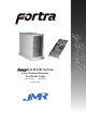
Force4 G6 RAID System 6-bay Desktop Enclosure Installation Guide May 29, 2002 • Revision B Patent Pending
Copyright Copyright 1998, 1999, 2001 by JMR Electronics, Inc. All Rights Reserved. No part of this publication may be reproduced, transmitted, transcribed, stored in a retrieval system, or translated into any language, in any form or by any means, electronic, mechanical, photocopying, recording or otherwise, without the express written permission of JMR Electronics, Inc. Sales and Ordering Information JMR Electronics, Inc.
Ta b l e o f Contents Table of Contents 1. Introduction 2/4/6/8/10/12/15-bay Product Family Features . . . . . . . . . . . . . . . . . . . . .1-1 6-bay Desktop Specifications . . . . . . . . . . . . . . . . . . . . . . . . . . . . . . . . . .1-2 Fibre Channel Features . . . . . . . . . . . . . . . . . . . . . . . . . . . . . . . . . . . . . .1-2 Loop Expansion . . . . . . . . . . . . . . . . . . . . . . . . . . . . . . . . . . . . . . . . . .1-2 Dual Loops (A & B) . . . . . . . . . . . . . . . . . . . . .
5. Blower Operation Blower Removal/Insertion . . . . . . . . . . . . . . . . . . . . . . . . . . . . . . . . . . . . .5-1 Blower Replacement . . . . . . . . . . . . . . . . . . . . . . . . . . . . . . . . . . . . . . . . .5-2 6. Power Supply Operation Power Supply Removal/Insertion . . . . . . . . . . . . . . . . . . . . . . . . . . . . . . .6-1 Power Supply Replacement . . . . . . . . . . . . . . . . . . . . . . . . . . . . . . . . . . . .6-2 7.
1. Introduction The FORTRA Force4 G6 RAID System is designed for use with a host system to provide a high-end desktop RAID storage solution. The following is a summary of the G6 RAID System features: • The FORTRA Force4 G6 RAID System is a six drive Desk Top enclosure that supports up to six 3.5" LP (Low-Profile) SCA (40-pin) drives. The Fibre Channel uses SFP transceiver connections to connect to an Intel PCI Fibre Channel 2 RAID controller supporting RAID 0 and 1.
FORTRA Force4 products use advanced mid-plane technology developed by JMR, that allows power supplies, drives, and all other enclosure components to interface into a single board. This provides superior performance and easy connectivity. The FORTRA Force4 G6 RAID System host interface supports 2G Fibre Channel interfaces as long as the drives have SCA connectors. Connection to the Intel PCI Fibre Channel 2 host system is made using SFP transceiver connectors.
Dual Loops (A & B) A single loop is required for unit operation however both loops can be used to connect to different hosts, dual host adapters, and other devices, for flexible and even redundant configurations. For specific connection and installation information, refer to Chapter 4. ID Selection 0-127 device ID addresses are addressable and can be easily set-up via ID jumpers for each slot. For specific connection and installation information, refer to Chapter 4.
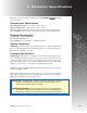
2. Har dware Specification This chapter covers specification information for the FORTRA Force4 G6 RAID System enclosure. Environmental Specifications Operating Temperature: 5°C to 40°C (41°F to 104°F) Storage Temperature: 0°C to 65°C (32°F to 149°F) Maximum ambient temperature is dependent on the recommended temperature to meet the MTBF rating as specified by the manufacturer of the installed devices.
Disclaimer The original product packaging has been tested and is safe under normal shipping circumstances. Reshipping the product without using the original product packaging will void the warranty. Do not ship the unit with canisters and/or power supplies installed in the enclosure as this will void the warranty and could cause damage to the unit and drives. The canisters should be packaged separately within the product packaging, as provided.
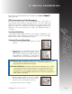
3. Device Installation This chapter covers Fibre Channel device installation for FORTRA Force4 G6 desktop enclosure. SCA Connection and Hot-Swapping The unit uses SCA-2 type connectors which provide a safe means of connection/disconnection when hot-swapping devices. In order to utilize this feature, the host adapter or RAID controller and host operating software must support the feature.
Drive Installation Device Mounting Holes (4) Status Indicators Handle Device mounting screws are included with the unit for device mounting. The JMR part number for the #6-32" mounting screws is HDS-01906. WARNING: Before device installation, alleviate any electro-static discharge by touching a grounded metal assembly. Static can be potentially damaging to enclosure components. WARNUNG: Berühren Sie vor der Festplatteninstallation geerdete Metallgegenstände, um elektro statische Aufladung abzuleiten.
4. Repeat steps 1 through 3 until all devices are installed. 5. Configure ID, and other options as required (see Chapter 4). 6. Establish host connection (see Chapter 4).
4. Fibre Channel Setup This chapter covers the Fibre Channel setup for the FORTRA Force4 G6 system. WARNING: Take care when connecting the unit to an AC power source to ensure that it is plugged-in to a circuit of the appropriate rating (110v or 220v). For safe operation, the circuit should have over-current protection to prevent damage to the unit in the event of circuit overloading.
Default Slot ID Drive Bay Slot 0 (top) Slot 1 Slot 2 Slot 3 Slot 4 Slot 5 Default ID/Jumper ID 0 / W1 ID 1 / W2 ID 2 / W3 ID 3 / W4 ID 4 / W6 ID 5 / W7 Setting Slot ID The ID for each slot can be set using jumpers located on the backplane of the unit. To access the jumpers the blower must be removed. To remove the blower refer to Chapter 5. NOTE: W1 sits above W2 behind a metal plate. W1 can not be seen in this photo.
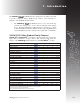
Fibre Jmp Jmp Jmp Jmp Jmp Jmp Jmp ID 0 1 2 3 4 5 6 0 C C C C C C C 1 O C C C C C C 2 C O C C C C C 3 O O C C C C C 4 C C O C C C C 5 O C O C C C C 6 C O O C C C C 7 O O O C C C C 8 C C C O C C C 9 O C C O C C C 10 C 0 C O C C C 11 O 0 C O C C C 12 C C O O C C C 13 O C O O C C C 14 C 0 O O C C C 15 O 0 O O C C C 16 C C C C O C C 17 O C C C O C C 18 C O C C O C C 19 O O C C O C C 20 C C O C O C C 21 O C O C O C C 22 C O O C O C C 23 O O O C O C C 24 C C C O O C C 25 O C C O O C C 26 C O C O O C C 27 O O C O O
Fibre Jmp Jmp Jmp Jmp Jmp Jmp Jmp ID 0 1 2 3 4 5 6 100 C C O C C O O 101 O C O C C O O 102 C O O C C O O 103 O O O C C O O 104 C C C O C O O 105 O C C O C O O 106 C O C O C O O 107 O O C O C O O 108 C C O O C O O 109 O C O O C O O 110 C 0 O O C O O 111 O 0 O O C O O 112 C C C C O O O 113 O C C C O O O 114 C 0 C C O O O 115 O 0 C C O O O 116 C C O C O O O 117 O C O C O O O 118 C O O C O O O 119 O O O C O O O 120 C C C O O O O 121 O C C O O O O 122 C O C O O O O 123 O O C O O O O 124 C C O O O O O 125 O C O O
CH A 1 CH B 1 CH A 2 CH B 2 Alarm Reset Button Power On/Off AC Input CH-A 1 Loop A connection 1. This is a SFP fibre channel connector used to connect to a host system or to an expansion chassis for Loop A. CH-A 2 Loop A connection 2. This is a SFP fibre channel connector used to connect to a host system or to an expansion chassis for Loop A. CH-B 1 Loop B connection 1. This is a SFP fibre channel connector used to connect to a host system or to an expansion chassis for Loop B.
5. Blower Oper ation This chapter covers operations of the blower for the FORTRA Force4 G6 units. Refer to Chapter 1 for blower specifications. The blower is easily removable. Failure to replace a non-working blower within a reasonable period of time may expose drives to extreme heat that could cause loss of data. WARNING: Blowers are a system critical component. Non-operating blowers should be replaced as soon as possible to avoid data loss or device failure.
3. Unplug the blower from the backplane. The connector is keyed so that it can be reinstalled correctly and has also been placed through a holder on the fan bracket to keep it out of the way during fan installation and removal. Reverse the steps to reinstall the blower. The following figure shows the blower intake access hole. Contact with the access hole must be avoided while the blower is running to prevent injury.
6. Power Suppl y Oper ation This chapter covers the operations of the power supply for FORTRA Force4 G6 units. For operation, the AC cord (included) must be connected to the AC Inlet at the back of the unit, and the On/Off switch must be switched ON. The Status LED on the power supply will light to indicate the power supply is functioning properly. If the power supply experiences a problem and cannot operate within its normal specifications, the Status LED will light ‘Red’ and an audible alert will sound.
Power Supply Replacement If the Power supply Status LED indicator is ‘Red’, the power supply may need to be replaced. The unit should be reset (turned on & off), and the power supply should be removed and then reinstalled. The AC cable connection in the back of the unit should be checked to ensure that the plug is firmly seated in the power supply. If the Status LED indicator is still ‘Red’, then the power supply should be replaced.
7. Installing the Intel PCI RAID Controller This chapter covers the installation of the Intel PCI RAID Controller that is shipped with the FORTRA Force4 G6 RAID System. The model number of the PCI RAID Controller is ICP Vortex number GDT8122RZ (ICP Vortex is a wholly owned subsidiary of Intel Corporation) Installing the PCI Controller To install the PCI Controller, perform the following steps: 1) Switch off the PCI computer and disconnect all cables. Ensure that the power cord is removed first.
8. Product Suppor t For current information on this product, including updates to the manual and technical support related issues, please contact the sales support section of our web page at www.jmr.com, or you can contact our Technical Support division directly at the address below. US Corporate Headquarters JMR Electronics, Inc. ATTN: Technical Support Division 20400 Plummer St. Chatsworth, CA 91311 Customer Support: (818) 739-1140 E-mail: techsupport@jmr.com Office Hours: Monday-Friday 8:00 A.M.
A ppendix A. Drive and Contr oller Manufacturers Drive Manufacturers Fujitsu Internet Address: www.fcpa.com Hitachi Internet Address: www.hitachi.com IBM (International Business Machines Corporation) Internet Address: www.ibm.com Maxtor Internet Address: www.maxtor.com Seagate Technology Internet Address: www.seagate.com RAID Controller Manufacturers Adaptec, Inc. Internet Address: www.adaptec.com Chaparral Network Storage Internet Address: www.chaparralnet.com Digi-Data Corporation Internet Address: www.
Host Bus Adapter Manufacturers Adaptec, Inc. Internet Address: www.adaptec.com Antares Microsystems Internet Address: www.antares.com Emulex Corporation Internet Address: www.emulex.com JNI Corporation Internet Address: www.jni.com QLogic Corp. Internet Address: www.qlogic.