
Quick Start Guide

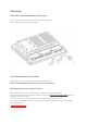

Interfaces
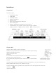
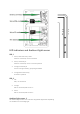
Connectors
From left to right:
• WWAN Main, SMA
• GNSS, SMA
• WWAN Aux, SMA
• USB2 x2, USB type A
• Ethernet, RJ45
• USB3.1, OTG, ADB, Display, USB type C
• USB3.1, USB type A
• RS232C, configurable 5V supply on pin1/9, D-Sub-9
• Isolated Power input, 9-72VDC, nominal input voltage 12-60VDC
– Pin 1 = Positive – Pin 2 = Remote On/Off – Pin 3 = Power Ground
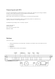
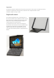
Power cable
Connect cable as shown in the picture below.
Remote may be connected to a remote switch or a vehicle ignition key for
automatic On/Off control where
high is on and low is off.
Important:
If not used for remote operation remote input pin must be connected to
positive input to enable operation.
JLT standard cable configuration: Red = Positive, White = Remote, Black =
Ground
The power cable must be dimensioned to handle up to 40 Watts, or use cable supplied by JLT.
Recommended cable area 0.75 mm
2
, AWG 18 or larger.
Important: Do NOT apply any solder to the cable ends. It will eventually make the connection
unreliable
and loose during use.