
Service Manual User guide

SECTION 6 - JLG CONTROL SYSTEM
3121262 – JLG Lift – 6-35
1001119262-A
Connector
Pin
FUNCTION
Type
J2 (Black)
1
Power Feed Thru to J1-1
Power I/O
2
Power Feed Thru to J1-2
Power I/O
3 Ground Power Output
4 Lock Pin NO Contact Digital Input
5 Lock Pin NC Contact Digital Input
6
Jib Transport #1 NO Contact
Digital Input
7
Jib Transport #1 NC Contact
Digital Input
8 Spare Input Digital Input
9 Spare Input Digital Input
10 Spare Analog Input Analog Input
11 Jib Level Up Digital Output
12 Jib Level Down Digital Output
Connector Pin
FUNCTION
Type
J4 (Grey)
1 Ignition Power Output
2 Ground Power Output
3 CANbus High Serial I/O
4 CANbus Low Serial I/O
5 CANbus Shield Power Input
6 Bootstrap Mode Digital Input
7 Ignition Power Output
8 Ground Power Output
Connector Pin
FUNCTION
Type
J1 (Grey)
1 Power Feed Thru to J2-1 Power I/O
2 Power Feed Thru to J2-2 Power I/O
3 Signal Feed Thru to J2-4 Digital Input
4 Master Ground Connect Power Input
5 Master Ignition Connect Power Input
6 CANbus High Serial I/O
7 CANbus Low Serial I/O
8 CANbus Shield Serial I/O
9 CANbus Terminator Serial I/O
10 CANbus Terminator Serial I/O
11 Ignition Power Output
12 Ground Power Output
Connector Pin
FUNCTION
Type
J3 (Green)
1 +5V Analog Reference Power Output
2 Jib Level Angle #1 Analog Input
3 Ground Power Output
4 +5V Analog Reference Power Output
5 Jib level Angle #2 Analog Input
6 Ground Power Output
7 +5V Analog Reference Power Output
8 Jib Swing Angle #1 Analog Input
9 Ground Power Output
10 +5V Analog Reference Power Output
11 Jib Swing Angle #2 Analog Input
12 Ground Power Output
Connector Pin
FUNCTION
Type
J5 (Brown)
1 Jib Lift Up Digital Output
2 Jib Lift Down Digital Output
3 Jib Swing Right Digital Output
4 Jib Swing Left Digital Output
5 Jib Telescope In Digital Output
6 Jib Telescope Out Digital Output
7 Spare Output Digital Output
8 Spare Output Digital Output
9 Ignition Power Output
10 RS232 Receive Serial Input
11 RS232 Transmit Serial Output
12 Ground Power Output
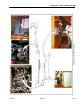
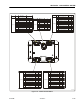
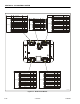
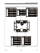
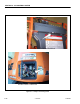
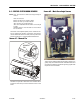
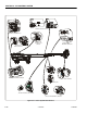
Figure 6-16. Jib Control Module