
Service Manual


SECTION 6 - TROUBLESHOOTING
6-30 – JLG Lift – 3121231
Code 27 - Auxiliary #2 - Disconnected
Check For These Obvious Conditions First:
• Is machine equipped with a component on the Auxiliary #2 circuit.
Code 28 - Reserved
Code 29 - Reserved
Code 30 - Traction Module - No Communication with Ground Control Module
Check For These Obvious Conditions First:
• Check if the communications cable connections, P5 connector on the Ground Control Module and round plug on the
Traction Control Module are seated properly in their sockets at each end.
• Check the Positive (+) (RED) and Negative (–) (BLACK) power cable connections from the Ground Control Module to the
Traction Control Module are tight and secure at both ends.
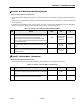
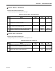
Table 6-31. Code 27 - Auxiliary #2 - Disconnected
STEP ACTION SPEC YES NO
1. Is machine equipped with a component on the Auxiliary #2 circuit. — Go to Step 3 Got to Step 2
2. At the Ground Control Module enter the programming mode, check if the
Auxiliary #2 open circuit detection is enabled.
Default = NO Disable It Replace Ground
Control Module
3. Check voltage at the P1 connector on the Ground Control Module between
pin-8 and pin-1. Is reading within specification?
2 - 4 V DC Replace Ground
Control Module
Go to Step 4
4. Remove the wire terminals at the Aux. #2 component, check continuity of
each of the wires from pins-8 and 1 on the P1 connector to the Aux. #2
component.
— Replace the
Component
Repair or
Replace Wiring
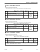
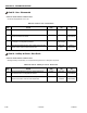
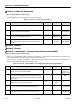
Table 6-32. Code 30 - Traction Module - No Communication with Ground Control Module
STEP ACTION SPEC YES NO
1. Check the voltage reading at the main power Positive (+)/Negative (–)
cable connection on the Traction Control Module.
24v DC Go to Step 2 Repair or Replace
Positive (+) or
Negative (–) Cable
2. Remove the communications cable, P5 connector at the Ground Control
Module and round connector at the Traction Control Module. Check conti-
nuity of all three (3) wires in the communications cable from end to end. P5
- Pins 2, 3, and 4.
— Go to Step 3 Repair or Replace
Wire(s)
3. With communications cable disconnected at both ends, check for continu-
ity between Pins 2, 3, and 4 of the P5 connector end.
— Repair or Replace
Wires
Go to Step 4
4. Plug the communications cable on the Traction Control Module to the round
socket on the opposite end of the module. Does this fix problem?
— Done Replace Traction
Control Module
5. Unplug the P5 connector at the Ground Control Module. Check voltage
between pins 2 (– lead-in) and 5 (+ lead-in). Is voltage within spec.
4.5v DC Done Replace Ground
Control Module